
Induction System Pressure Control
Patriot State was the training ship of the Massachusetts Maritime Academy from 1986 to 1998.
The primary purpose of the extraction steam systems is to provide steam for feed heating and to improve the overall efficiency of the steam plant.
Bleed steam is available from the H.P. and L.P. turbines at four locations.
H.P. Bleed steam may be extracted at the second stage of the H.P. turbine at a design pressure of 191 psi, and is directed to the fourth stage heater.
I.P. Bleed steam may be extracted at the fourth stage of the H.P. turbine and provides steam at a design pressure of 106 psi to the third stage heater and the contaminated evaporator.
Crossover Bleed steam may be extracted from the crossover between the H.P. and L.P. turbines at a design pressure of 37 psi, and used as make-up steam for the auxiliary exhaust system.
L.P. Bleed steam may be extracted from the L.P. turbine at a design pressure of 9.4 inches Hg, and is used to heat condensate in the first stage heater, and feed water in evaporators one and two.
The actual pressures available at the bleed points varies with the load on the turbines. When the main engine is producing its design power, the pressures at the bleed points are at their design values. Since steam temperature varies with steam pressure, the feed heaters operate best when the ship is at its design conditions. When the ship is slowed, the pressures and temperatures at all the bleed points drops accordingly. Since the Patriot State rarely operates speeds the Santa Mercedes was designed for, our feed heating efficiency is reduced.
Induction System Pressure Control

High, Intermediate, and Low pressure Bleeds
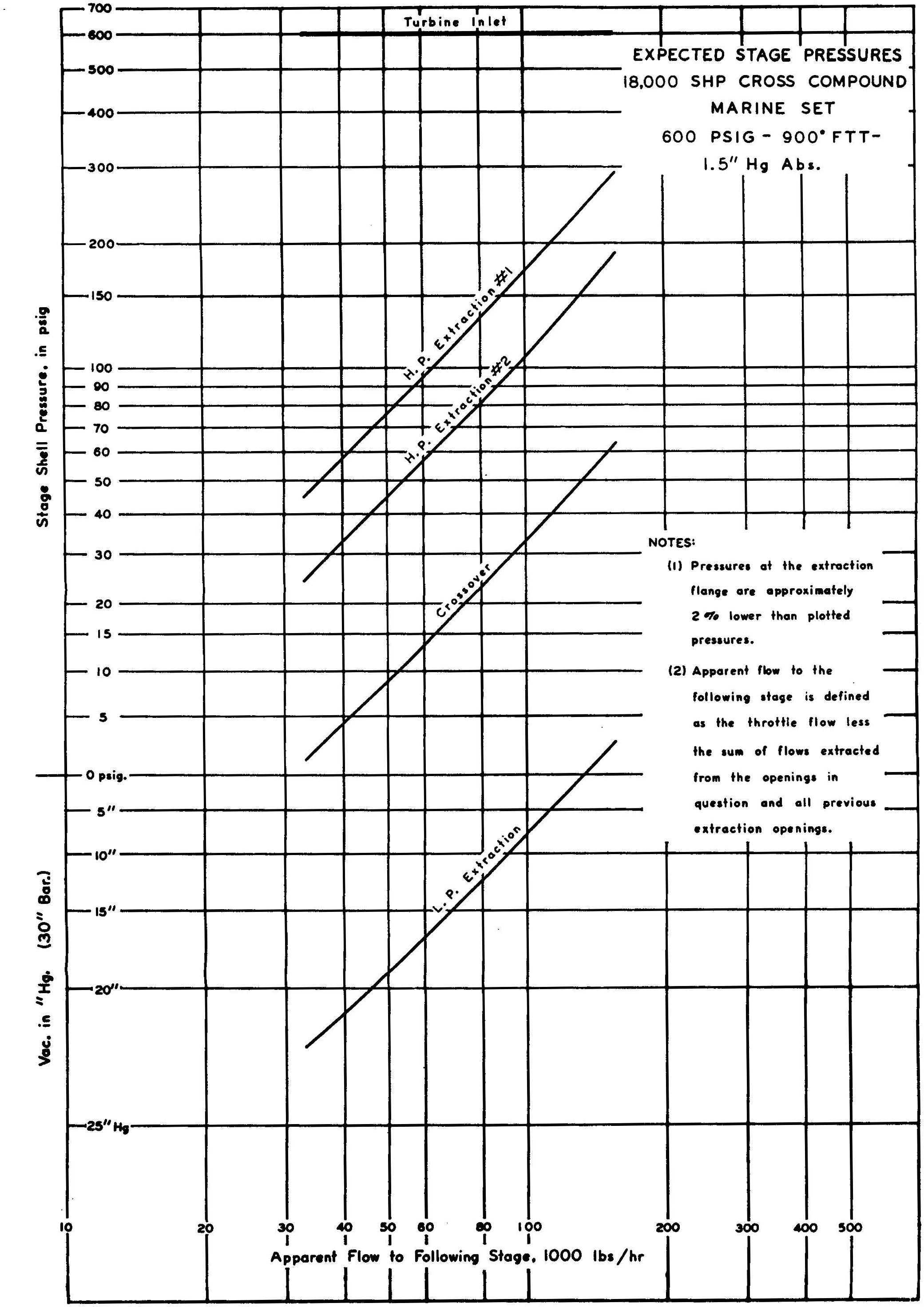
Extraction Pressure Curves
The training ship originally had three turbine driven refrigeration compressors which were used to refrigerate the cargo in three and four holds. Rather than discharging the turbine exhaust steam directly to a condenser, these turbines were designed to exhaust to the main engines at the crossover, where the remaining energy in the steam could be utilized by the L.P. turbine. This system is known as the reefer induction system.
When the ship is at sea and the reefer turbines are running exhaust steam from cargo turbine is introduced into the crossover through an induction valve, which also supplies make-up steam to the auxiliary exhaust system.
The induction valve is an air operated valve (air opens) which is wide open when the crossover pressure is above 28 psi. When the throttles are closed, the crossover pressure drops. When the crossover pressure drops below 28 psi, the induction valve starts closing and is fully closed at 25 psi. This prevents the reefer induction steam from spinning the L.P. turbine when the main throttle valve is closed.
When the induction valve closes, then compressor turbine exhaust is automatically dumped to the auxiliary condenser at 48 psi.
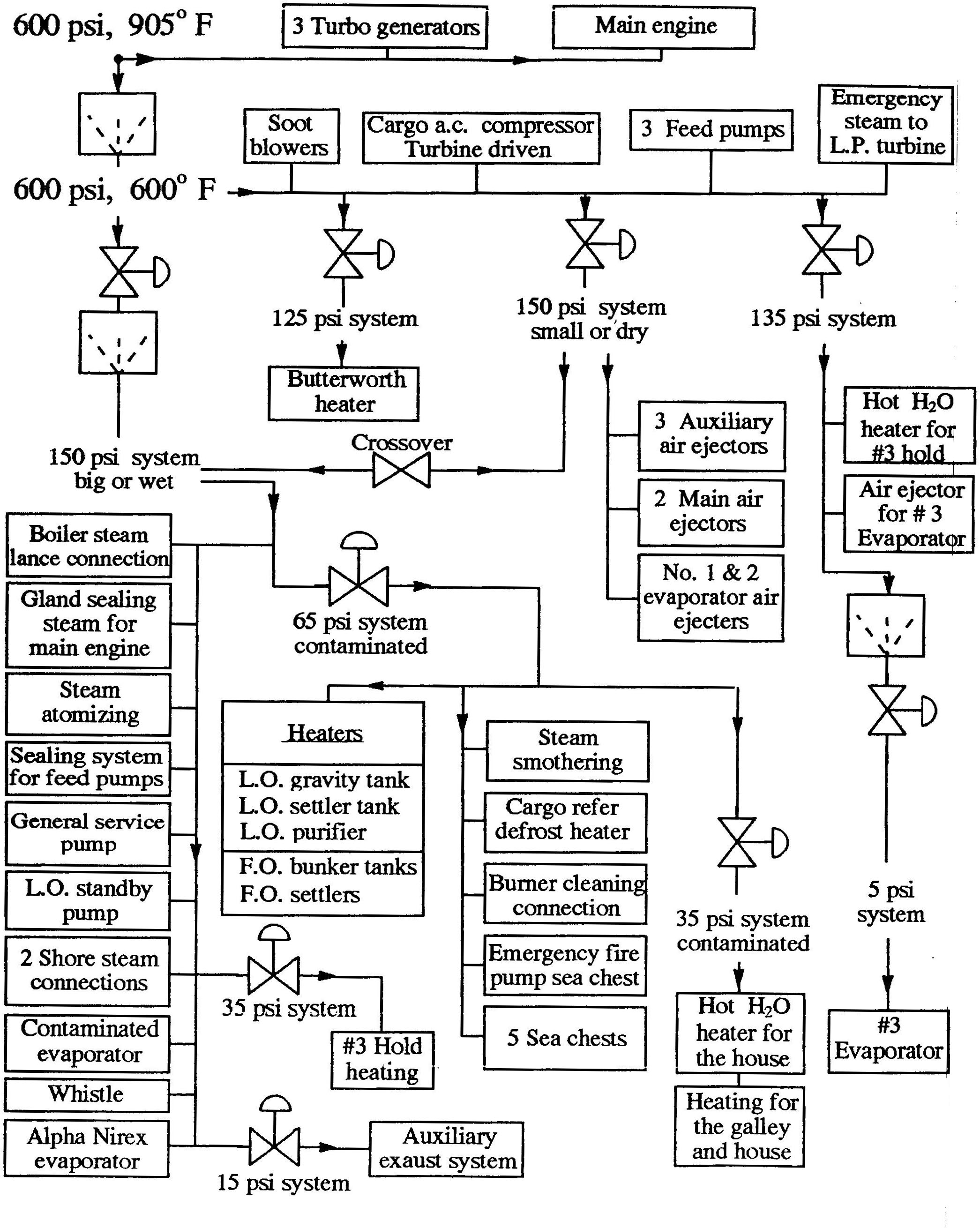
Steam System Summary
Direct comments to William Haynes whaynes@maritime.edu
Mon, Jul 1, 1996
TSPS Engineering Manual ©1995 Massachusetts Maritime Academy