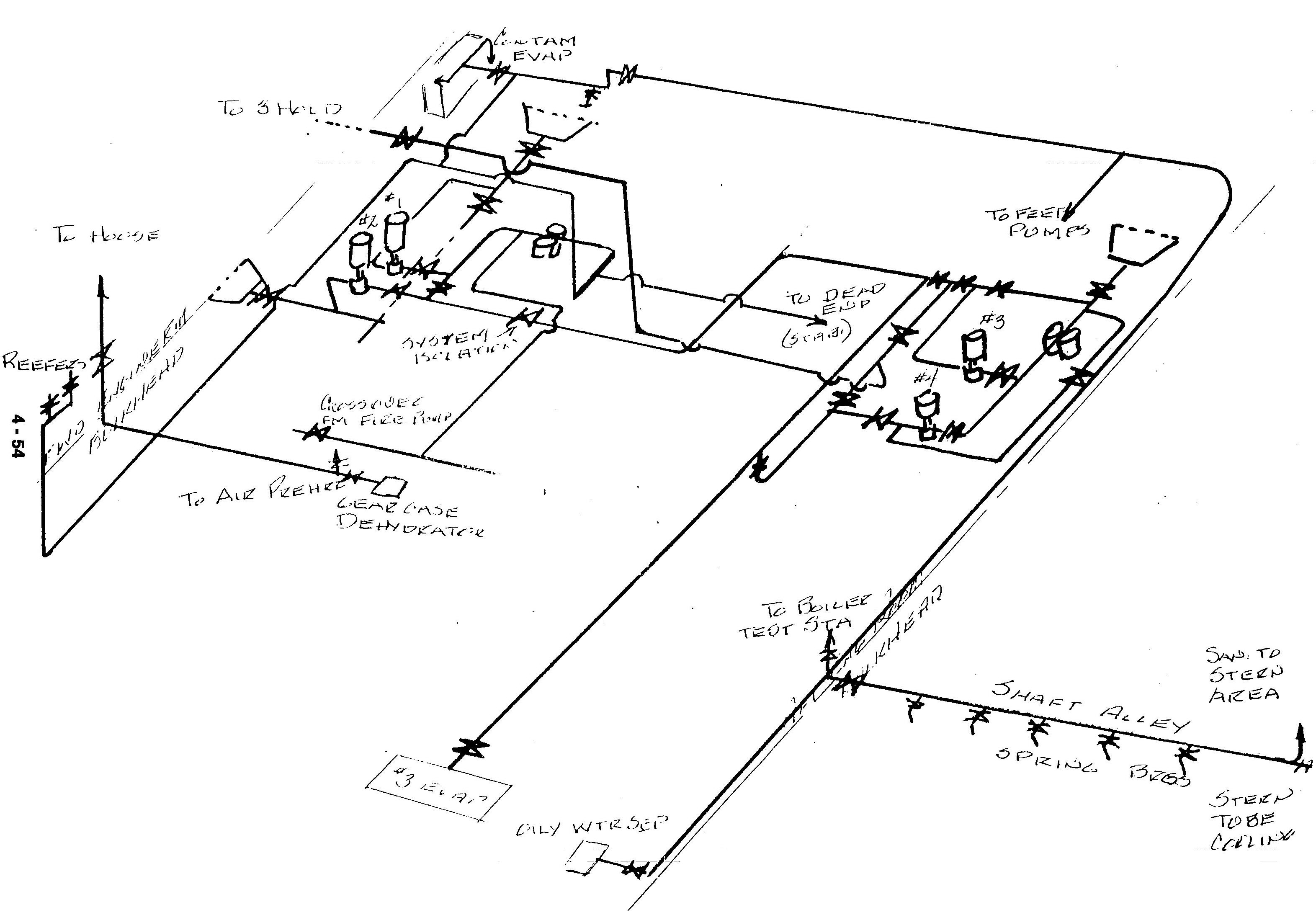
Sanitary System
Patriot State was the training ship of the Massachusetts Maritime Academy from 1986 to 1998.
The salt water and sanitary service system supplies salt water for flushing water-closets, urinals, slop sinks, and for miscellaneous cooling services. The water is supplied by four vertical, single stage, centrifugal, motor driven pumps.
The following equipment are served by this system:
The original system of the ship consists of two horizontal, single stage centrifugal, motor driven pumps, each with a 375 gpm capacity and a total head of 142 feet. They can take a suction either from a high or low sea chest and discharge it into a common line. A relief valve is provided in this common line so the combined pump discharge doesn't exceed 80 psi.
The new system, installed when the ship was converted, consists of two vertical, single stage, centrifugal motor driven pumps, each with a 350 gpm capacity and a total head of 140 feet. These pumps discharge into a common line which is connected to the older system. The new pumps, unlike the old ones, can only take a high sea chest suction. However, it is taken through a duplex basket type strainer.
The sanitary system has a crossover from the fire main system to permit operation of the sanitary system with the fire pump.
Under normal operations, this system may be handled by only one pump with another one all set up and ready to go as a stand-by. However, if the need arises, two pumps from the system may be used simultaneously.
The two Ingersoll-Rand sanitary pumps are in drip proof housings. They are vertical, motor driven, single stage, centrifugal pumps with a 375 gpm capacity and a 142 foot total head. They run at 3450 rpm, driven by an Ingersoll-Rand 20 horsepower, 440 volt, 60 cycle, 3 phase motor.
The two Baldor sanitary pumps are also in drip proof housings. They are vertical, motor-driven, single stage, centrifugal pumps with a 350 gpm capacity and a 140 foot head. They run at 3525 rpm, driven by a Baldor 20 horsepower, 240/440 volt, 60 cycle, 3 phase motor.
Sanitary System
The firemain system is one of the most important systems aboard the ship. Its main purpose is to supply large quantities of sea water to combat fires. It also serves as an emergency or stand-by supply for salt water and sanitary service system. The firemain is also used to supply the clean ballast system. The firemain includes all valves and piping from the discharge nozzles of the pumps to root valves in the branches of the services supplying water to the system, including all hose, hose valves and nozzles which in effect are extension of the system. Cut-out valves are installed where necessary to allow segregation of damaged sections of the firemain for maintenance or repair.
The firemain is served by three pumps which take suction from the sea and discharge to the firemain. The firemain runs forward and aft from the machinery space through the pipe tunnel forward and the shaft alley aft to supply risers forward, midship, and aft. Individual branches from the risers terminate at fire hydrants located generally on the main deck forward and aft, the house, and the forecastle deck.
Stand-by water supply to the salt water and sanitary service system is provided from the firemain through a 125/50 psig pressure reducing valve. This reducing station is fitted with a valved by-pass.
The Fire Pump, located in the machinery space, is a motor driven vertical, centrifugal type pump built by Warren Pumps, Inc., with a capacity of 500 gpm at 280 feet total head. This pump takes suction from the sea and discharges to the firemain. The pump discharges through a 5" line to the firemain through a stop-check valve and piping fitted with a relief valve set at 125 psi. The relief valve discharge is led back to the pump suction.
The Emergency Fire Pump, located in shaft alley, takes suction through a 6" line from an emergency sea chest located near the pump, and discharges to the firemain through a stop-check valve. This pump is a motor driven, vertical, centrifugal type unit built by Warren Pumps, Inc., with a capacity of 500 gpm at 280 feet total head. A relief valve set at 125 psig is provided at the pump discharge. The pump also has a 3/4" recirculating line that discharges to the emergency sea chest.
The Fire and Butterworth pump is a motor driven, vertical, centrifugal type unit also built by Warren Pumps, Inc., with a capacity of 600/300 gpm at 280/336 feet total head. The pump takes suction from the sea and discharges to either the firemain or Butterworth system depending on the set position of the valves in the discharge line. The pump discharges to the firemain through a stop-check valve and piping fitted with a relief valve set at 125 psig. The relief valve discharge is led back to the pump section. The Fire and Butterworth pump may also be used for salt water and sanitary service system. The Butterworth system provided a means, in conjunction with the Butterworth heater, to supply heated sea water to use in cleaning the liquid cargo tanks.
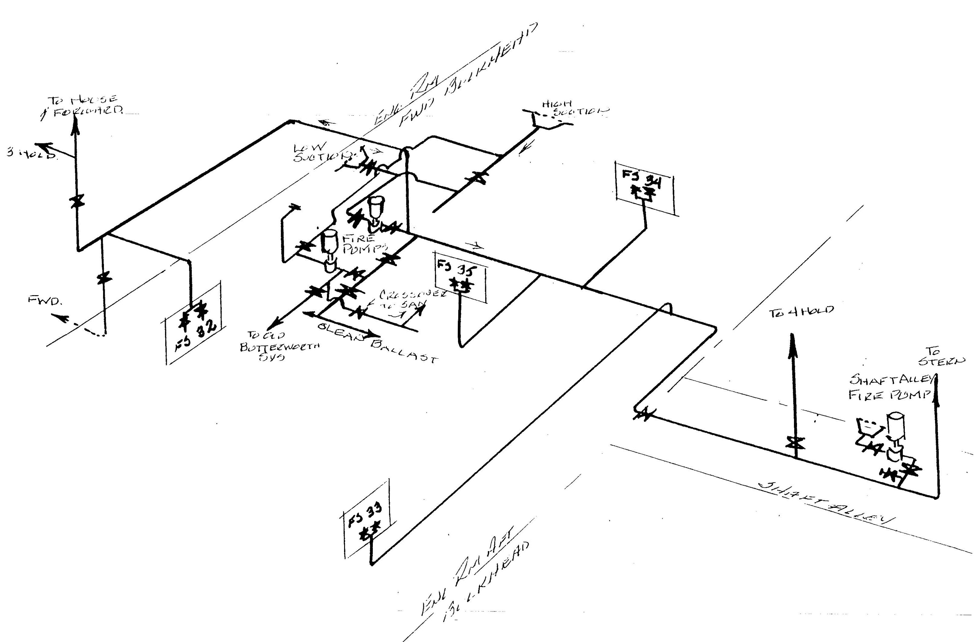
Firemain in Engineroom
Direct comments to William Haynes whaynes@maritime.edu
Mon, Jul 1, 1996
TSPS Engineering Manual ©1995 Massachusetts Maritime Academy