Compressed Air System (partial)
Patriot State was the training ship of the Massachusetts Maritime Academy from 1986 to 1998.
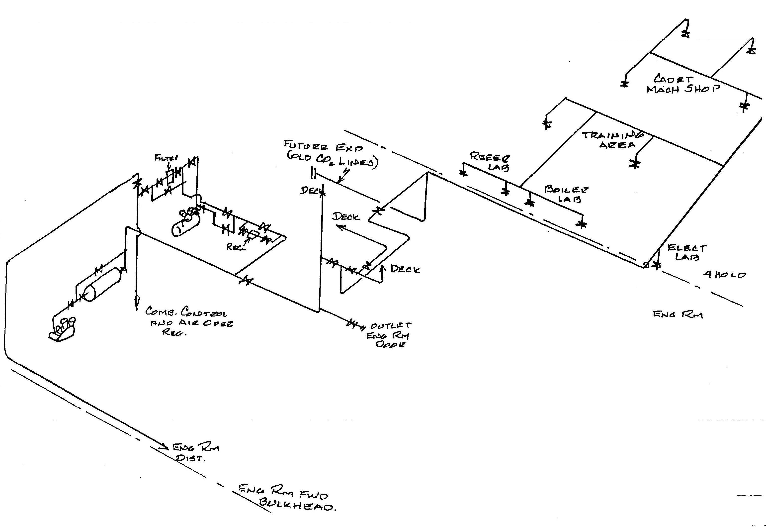
The compressed air systems supply all air operated valves, combustion and feed water controls, soot blow controls, retractable soot blowers, and general services throughout the vessel.
Three compressed air systems are installed on the ship: the ship's service system air including deck air, the control air system, and the emergency air system.. All systems consist of motor driven compressors, air receivers, moisture separators, relief valves, and interconnecting piping with valves, line filters, and accessories including service connections.
The ship's service and control air systems are cross-connected in order that stand-by service may be provided for the control air system. The cross-connection line consists of a stop-check valve, a stop valve, an air filter, a 125/110-75 psi pressure regulating valve, a test gauge connection, and a stop check valve, in that order.
There are three air receivers, which act as temporary storage and surge tanks, provided they are fabricated of steel with disked ends, and are equipped with pressure gauges, relief valves, drain valves, and connections for cleaning and inspection. The capacity of each receiver is:
The ship's service air system is provided by the main air compressor , which discharges directly to the main air receiver, and the deck air compressor both located on the compressor flat in the engine room. A receiving tank connects directly to the ship's service compressed air main.
This ship's service air main supplies the various air services including the pneumatically operated valves in shaft alley, soot blowers, combustion controls, hydro-pneumatic tanks, expansion tanks, galley door operators, and various hose connections. The ship's service compressor normally supplies this system. The deck air compressor is used to supply deck hose connections during periods of heavy demand for air on deck, and it can be used to supply the entire system in emergencies.
The piping arrangement between the ship's service compressor and the air receiver consists of a moisture separator, a relief valve set at 125 psi, a lift-check valve, a pressure gauge, and gate valves. A by-pass is provided around the air receiver to the ship's service air main. A 125 psig relief valve is fitted to the compressor discharge and a 125 psig relief valve is located on the air receiver tank
The ship's service hose connections are fitted with a moisture separator and a hose valve. Where air is supplied for cleaning purposes, an additional hose valve is installed, served through an orifice at reduced pressure.
Compressed Air System (partial)
The ship's service air compressor has a capacity of 155 cfm at 125 psig, and runs at 770 RPM off of a Westinghouse 40 horsepower, 1800 RPM, 3 phase, 60 cycle motor. .
The deck air compressor was installed in 1992. It is a double screw, single stage air pump with a rated capacity of 163 cfm at 125 psig, belt driven by a 40 HP three phase motor. Both compressors are manufactured by Ingersol-Rand.
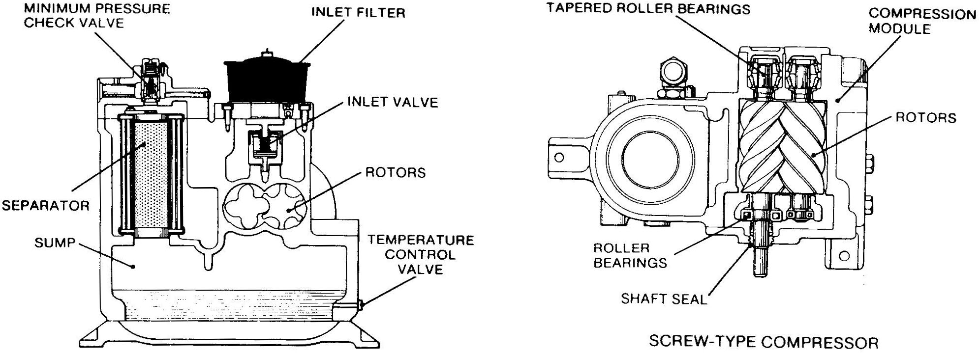
Air Compressor, screw type
The deck air compressor is a screw type air compressor. Compression is created by the meshing of two helical rotors on parallel shafts, enclosed in a heavy-duty cast iron housing, with air inlet and outlet ports located on opposite ends. The male rotor has four lobes 90° apart, and the female rotor has six grooves 60° apart. The grooves of the female rotor mesh with, and are driven by the male rotor.
Air flows into the compressor through a replacable paper element filter and past an inlet valve in the compressor suction before it is drawn into the rotors. The air is compressed, leaves the rotors, flows through the coolant/air separator and then leaves the top of the separator housing through a minimum pressure check valve. The air then passes through an air-cooled after-cooler and a moisture separator to condense and remove water from the compressed air, and then into the reciever.
The compressor uses a specially formulated coolant to perform three functions. It lubricates the bearings and contacting surfaces of the rotors, it seals the rotor clearances, and it cools the compressed air. Compressor discharge pressure is used to circulate the coolant from the sump through a cooler and filter, and then back to the rotors.
The deck air compressor uses a computerized capacity control system to match compressor output to system demand. The capacity of the compressor is varied with the inlet valve in the compressor suction. When the inlet vavle is closed, less air is compressed, and the compresser power requirement is reduced.
Two capacity contol modes are available. In the on-line/off-line mode, the inlet valve is wide open and the compressor delivers full capacity and operates at maximum efficiency until the desired reciever pressure is achieved, then the inlet valve closes and the compressor operates at minimum power until the reciever pressure drops again. In the modulating mode, as the reciever pressure rises the inlet valve is throttled and the compressor capacity and power consumption is reduced, until the compressor output just matches the system demand.
An Automatic Selector control is provided which continuously monitors the air system demand and selects the optimum mode according to current conditions. It allows the compressor to operate in its most efficient mode without attendance, and thereby reducing power costs to a minimum.
The control air system is supplied by a compressor with a 40 cfm capacity at 100 psi. The receiving tank discharges to the control air system via a salt water cooled control air dehumidifier and filter, a lift check valve, and a gate valve.
The control air main supplies the various pneumatically controlled valves and device including superheater temperature control, desuperheater temperature control, auxiliary exhaust controls, air conditioning controls, Butterworth heater drain regulator, first, third and fourth stage feed heater drain regulators, cargo tank heating controls, fresh water drain collecting tank regulator, main feed pump governor, feed water control, contaminated water evaporator control, salt water pressure reducing valve and emergency supply valve to 65 psi steam system.
A dehumidifier and filter unit is provided in the discharge line from the control air tank. It consists of a condenser-separator and a disposable filter cartridge. The purpose of this unit is to remove oil, dust, and water from the control air, thereby assuring a clean, dry air supply for the system. Cooling water for the condensifilter is supplied from the salt water and sanitary system. Condensation is drained to the bilge automatically via a magnetic pneumatic power trap, and oil and dust particles are absorbed in the disposable filter.
The Ingersoll Rand control air compressor, supplying 40 cfm at 100 psig runs synchronously off of a General Electric 15 horsepower, 1800 RPM, 3 phase, 60 cycle motor. A pressure gauge which mounted on the main gauge board and a relief valve set at 110 psi are provided.
The emergency air supply is provided by an emergency air compressor with a capacity of 13.2 cfm and a discharge pressure of 125 psi located in the emergency generator room. The compressor is connected to its air receiver through a check valve into a multiport valve. This multiport valve enables the system to be fed directly from the compressor or from the air receiver. A relief valve is mounted on the main line set at 125 psi and done on the air receiver set at 125 psi. The emergency air compressor supplies compressed air for control valves (in case of failure of ship's service compressed air system) to the fuel oil tanks.
Before starting any air compressor, drain all moisture from the inter-cooler, after-cooler, and receiver, and verify that there is sufficient oil in the crankcase. While operating, periodically drain moisture from the receiver and verify the operation of the cut-in and cut-out switch.
Under normal operation, the control air system is lined up with both ship's service and combustion control air compressors in the automatic mode, and the cross-connection open. The service air compressor, through the cross connection and the air pressure reducing valve, will maintain the combustion control air receiver between 92 psi and 100 psi. If the combustion air pressure drops to 85 psi, the control air compressor will automatically start to restore the pressure. It will stop when the control air pressure reaches 100 psi. If the control air pressure drops below 80 psi, an alarm will sound in the fireroom.
Direct comments to William Haynes whaynes@maritime.edu
Mon, Jul 1, 1996
TSPS Engineering Manual ©1995 Massachusetts Maritime Academy