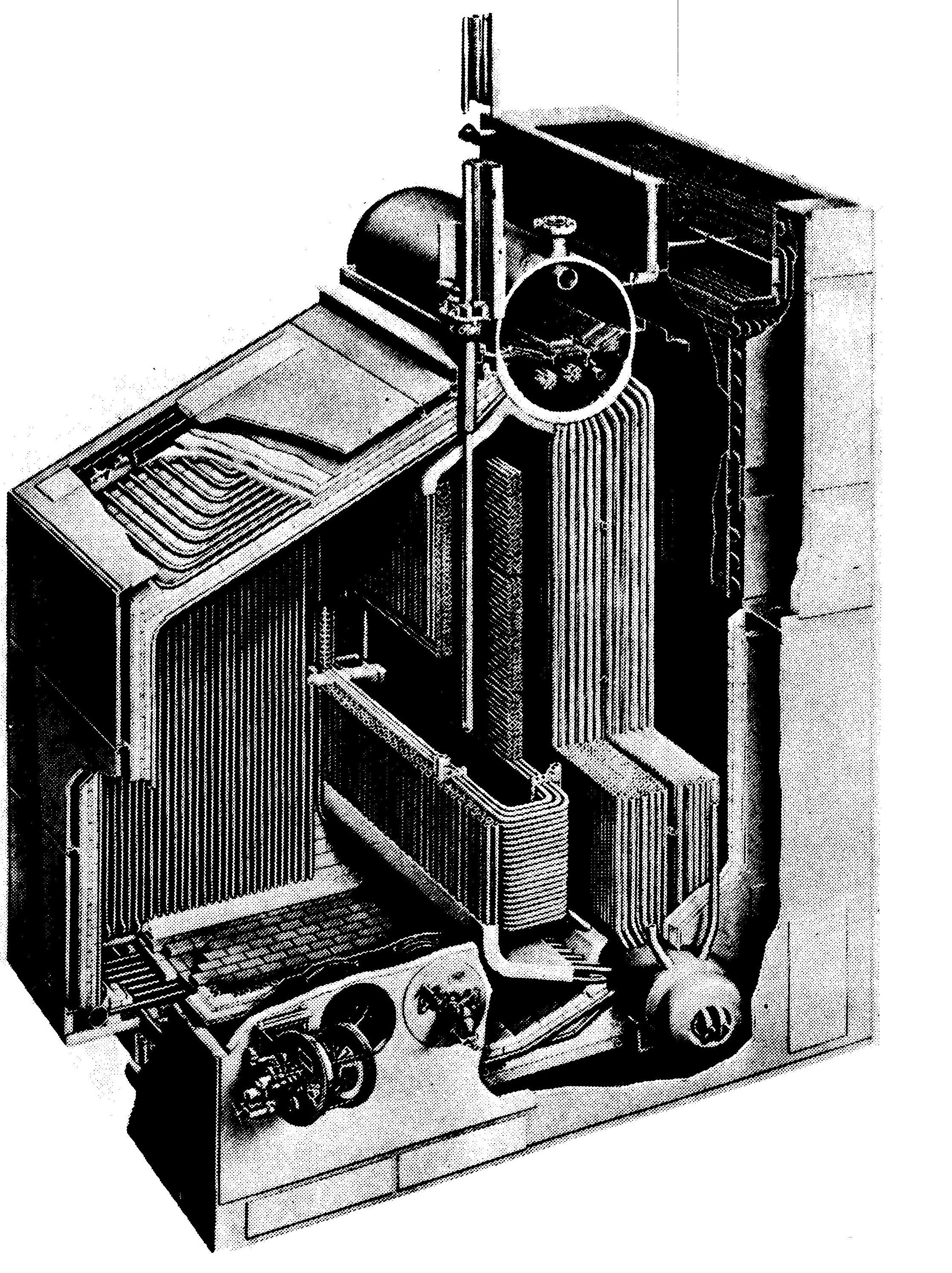
Two-drum, Single-furnace Boiler with horizontal superheater
Patriot State was the training ship of the Massachusetts Maritime Academy from 1986 to 1998.
On the Patriot State, steam is produced for propulsion and other requirements by two Babcock and Wilcox two-drum, oil fired marine water tube boilers, that are capable of producing 108,000 lbs/hr of superheated steam at 620 psi and 905° F. Each boiler is fitted with four registers and steam atomized burners, soot blowers, smoke indicators, water gauges, high and low water alarms, and safety valves. Originally the boilers were fitted with control desuperheaters to maintain design temperature at the superheater outlet under varying operating conditions. The control desuperheaters were removed when the ship was converted to the training ship, and consequently, we have to carefully watch the superheater outlet temperature during high steaming conditions.
The boiler furnace is made up of tubes covering four walls and a floor. The side wall bends upward toward the steam drum and therefore also form the furnace roof. The side, front and rear walls are water cooled with bare tube construction. The floor is water cooled by tubes installed below two courses of firebrick.
The front wall consists of 2" O.D. bare tubes expanded and belled into the upper and lower front wall headers. The lower front wall header is supplied with water by the 2" O.D. floor tubes, which connect with the water drum. Two 4-1/2" O.D. riser tubes connect the upper front wall header with the steam drum.
The side wall and roof consist of 2" O.D. bare tubes expanded and belled into the sidewall header and the steam drum. The side wall header is supplied with water by the upper row of 2" O.D. floor tubes, which connect with the water drum.
The rear wall consist of 2" O.D. bare tubes expanded and belled into the upper and lower rear wall headers. The lower rear wall header is supplied with water by the lower row of 2" O.D. floor tubes, which connect with the water drum. Three 4-1/2" O.D. riser tubes connect the upper rear wall header with the steam drum.
The floor tubes consist of two rows of 2" O.D. tubes beneath the floor firebrick. They supply water from the water drum to the side and rear wall headers.
These arrangements give complete side, front, rear and floor tube circulation independent of the main circulation circuit in the boiler generating tubes.
Two-drum, Single-furnace Boiler with horizontal superheater
A standard Babcock and Wilcox triple-plate perforated baffle is installed in the steam drum. Its purpose is to aid in the delivery of clean dry steam to the superheater via the dry pipe. This will aid in avoiding the deposit of solids on the surfaces exposed to the steam. The baffle plates themselves extend longitudinally along the interior of the drum and allows for adequate areas for the flow of released steam. The chemical feed pipe is used to inject boiler chemicals into the steam drum while the boiler is in operation, and also as a sampling pipe for testing the boiler water. The chemical feed pipe extends almost the entire length of the drum below the normal water level and connects to the chemical feed piping nozzle on the end of the drum. A row of 1/8" diameter holes are drilled along the top centerline of the pipe to pass the chemicals. There is a separate boiler water sampling line which can also be used when putting the boiler on continuous blow. The continuous blow is to the bilge. There is no surface blow line on these boilers.
The dry pipe is suspended along the top centerline inside the steam drum. It is perforated along its upper surface with rows of 3/8" diameter holes and drain holes are provided in the bottom of the pipe at each end. Steam enters the dry pipe through the upper perforated area and leaves the pipe through the connection which leaves from the top of the drum to the superheater. The dry pipe serves a dual function; it reduces moisture carry-over and provides for an even withdrawal of steam from the water surface.
The internal feedline is that part of the feedline within the steam drum. It extends approximately 90% the length of the drum, below the normal water level, and is connected to the feed supply nozzle. It has one row of 1/2" diameter holes along the pipe to introduce the feedwater into the steam drum evenly throughout to prevent thermal shock.
The superheater is made up of a series of 1-1/4" O.D. U-bent tubes arranged in four loops and connecting two superheater headers which are supported at the rear of the boiler. The U-tubes extend the full depth of the boiler and are supported by four 3/4" O.D. support tubes. The steam will make six passes of the superheater.
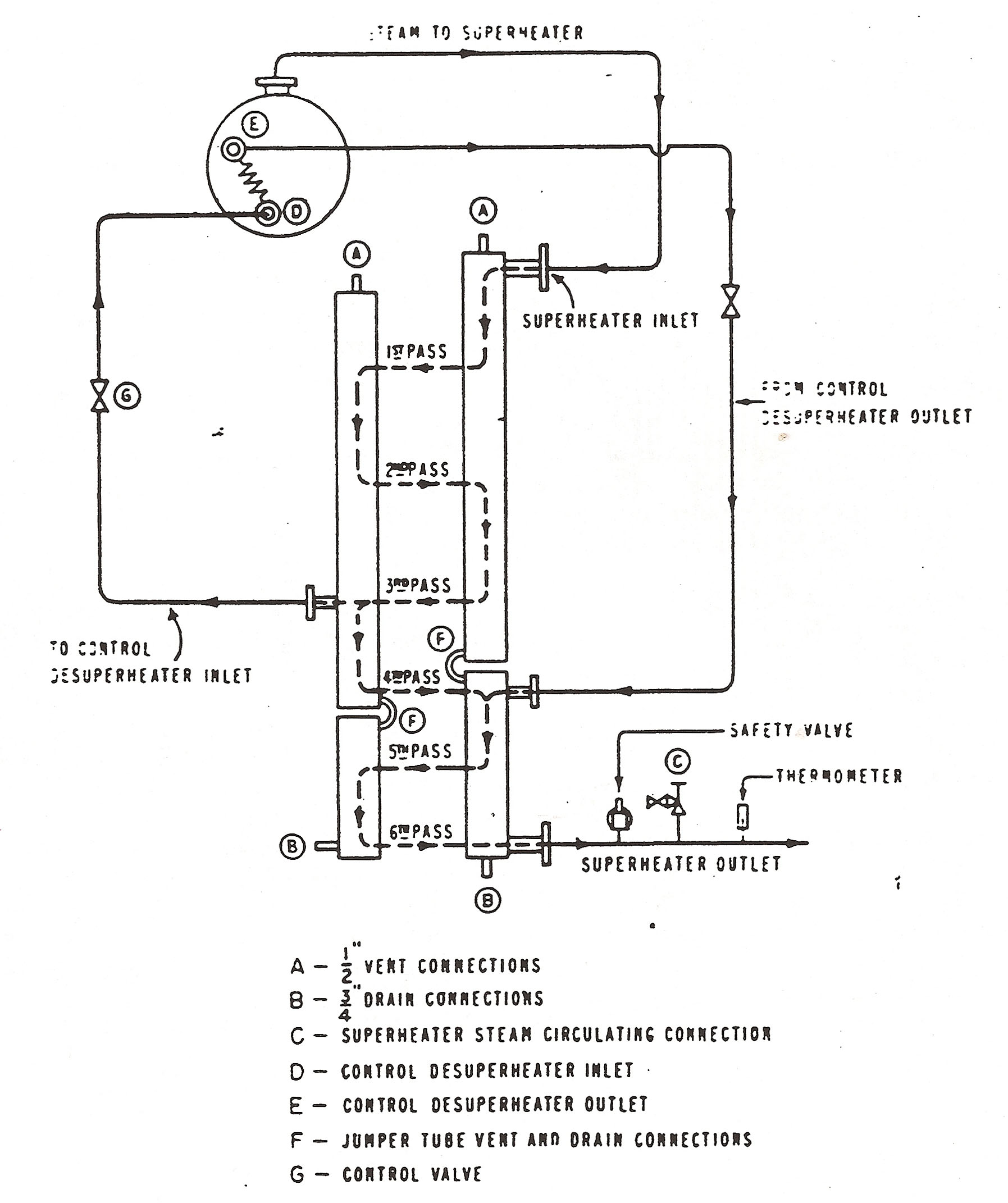
Superheater Arrangement, showing flow path, vents, drains and Control Desuperheater Piping (removed)
The boiler proper consist of a 54" steam drum and a 30" water drum connected by a generating bank of 18 rows of 1-1/4" O.D. tubes bent at the ends so they enter the boiler drums radially for expanding and belling.
The bank is arranged so that the furnace gases make a single pass over it before entering the uptakes. Also, there are two rows of 2" O.D. tubes between the furnace and the superheater which screen the superheater from the direct radiation of the furnace gases.
Safety valves are installed on both boilers to prevent the pressure in the boiler from rising above a safe working pressure. To insure positive flow through the superheater, the superheater safety valves will pop before the two drum safety valves. The safety valves from both boilers connect to a common escape pipe. A superheater outlet safety valve is installed at the superheater outlet and is the one that will lift when the first drum valve pops - and remain open until the last drum safety is seated. The safety valves on a boiler must be of sufficient size and number to reduce the steam drum pressure to a safe level at full firing rate with the boiler completely cutoff steam lines.
% Blowdown = F((lifting pressure - reseating pressure) x 100,(working pressure)) To insure the valve is free, each safety valve or safety relief valve has a lifting device so the valve disk may be lifted from its seat by hand. There must be at least 75% full working pressure on the boiler before the hand easing gear is used.
Safety valve must never be locked or gaged other than when conducting a hydrostatic pressure test.
The safety and relief valve escape system consists of two escape pipes led from the machinery spaces through the inside of the outer stack to the atmosphere.
Eight inch escape piping is used from boiler safety and superheater safeties and ten inch escape piping from remaining steam systems. Low points in escape piping drain to the bilge.
Boiler Safety Valve Settings        Lift       Reset
      #1 Drum, 2-1/2" Valve              750 psi    728 to 712 psi
      #2 Drum, 2-1/2" Valve              745 psi    723 to 708 psi
      Superheater Safety Valve 1-1/2"    645 psi    626 to 612 psi (3 to 5%)
Protection against excessive superheater temperature while lighting off and bringing the boiler up to pressure is provided by means of a 1" superheater vent line, which permits the circulation of steam through the superheater to atmosphere through a root and throttle valve connection. These valves provide two valve superheater protection in the vent line to insure against steam leakage to atmosphere once the boiler is up to operating pressure.
The superheater temperature control equipment has been removed from the Patriot State boilers, but is similar to equipment found on many ships, and is described here for reference only.
The superheater outlet temperature was maintained by diverting steam from the inlet of the fourth superheater pass, through a superheating coil located in the boiler steam drum and then back to the inlet of the fifth superheater pass.
The control equipment was capable of maintaining superheater outlet temperature within 5° F. of the set point during a superheater outlet temperature change of one °ee in three seconds. The control was normally set to maintain 905° F. at the superheater outlet.
The controls consisted of a pneumatic temperature transmitter which sensed the superheater outlet temperature and transmited an air pressure proportional to this temperature to a pneumatic controller. The controller established an air pressure proportional to the difference between the superheater outlet temperature and a set temperature, and transmitted this pressure via a valve positioner to a disphragm operated valve to control the flow of steam through the control desuperheater. The valve positioner accurately and rapidly positioned the valve in response to the controller. A remote control station was provided to establish a set point for maintenance of the superheater outlet temperature.
A stop valve was provided at the outlet and inlet of the 4" superheater temperature control line and a 1/2" circulating by-pass around the diaphragm operated control valve.
A control desuperheater controlled and maintained the superheater outlet temperature within a preset range. This was necessary when the boilers were operating near their maximum firing rate. The outlet temperature of an uncontrolled superheater would tend to rise according to the firing rate.
Since this ship, in its present condition, no longer has a control desuperheater we are left with an uncontrolled superheater. The superheat temperature must be watched closely and may be controlled to a certain extent by using three factors: excess air, feedwater temperature, and which burners we use. Too much excess air used for combustion will raise the superheat temperature, and therefore must be closely watched. Higher feedwater temperature entering the boiler will lower the superheater outlet temperature, so the third and fourth stage heaters should be utilized to their fullest potential. When operating the boilers with only two burners, it is undesireable to have the two inside burners firing. These burners, being closer to the superheater will transfer more heat to the superheater bank increasing the temperature.
Each boiler has the following steam soot blowers:
Soot blowers enable the operating personnel to keep the boiler tubes free of soot deposits. The soot blowers are installed adjacent to and between the tubes. They are used while the boiler is steaming and act on the fire side of the tubes. Soot blowers are pipes with nozzles along their length. Soot blowers can either be permanent or retractable, and they can rotate up to a full 360° during operation. Steam for operation is supplied by the 600 psi auxiliary steam line.
When secured, the piping in the nonretractable soot blowers is kept cool with the use of a steady flow of air passing through them. The air is supplied by the positive pressure in the boiler double casing. This air flow prevents deterioration by cooling the soot blower and also cleans, as well.
The nozzles on the soot blower element are so arranged that they do not spray the high velocity steam directly on the tubing which would cause erosion.
The steam is cut in and out to the element by the soot blower head which has a valve operated by a cam and a rocker arm. The cam and element can be rotated by a hand operated endless chain or an air motor. Soot blowers are blown in a predetermined order, to follow the gas flow. The speed of the forced draft blowers are increased, when blowing tubes, to help produce a force of air to carry the soot up the stack.
A raise in stack gas temperature would indicate poor heat transfer in the boiler itself. Soot must be removed from the tube surfaces, at least daily, with the soot blowers. If the rotating element of the soot blowers is non-functioning, do not use the blowing unit. The stationary nozzle will direct steam in only one direction and severe tube erosion could occur.
Patriot State has no surface blow line installed.
Bottom blow valves are installed at the bottom of each water drum and water heaters. The valves used in bottom and surface blow down are used to reduce total solids or grease, dirt or to just drain off excess water when shut down.
When blowing down a boiler, you must never allow the boiler level to go out of sight in the gauge glass. A boiler should never be given a bottom blow while steaming unless it is an emergency. This is because circulation could be interrupted.
The most effective procedure for blow down of the boiler is to secure the boiler for an hour and then give a short blow down. This should be repeated every half hour until sufficient sludge is removed. A rest period between the multiple short blows will allow the sludge to settle each time and the blow down will be far more effective.
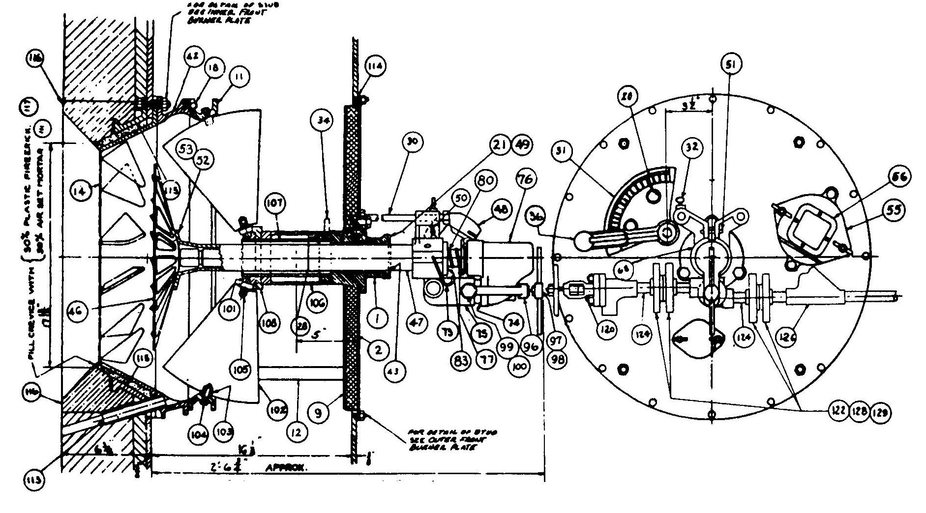
The burners onboard the Patriot State are manufactured by Babcock and Wilcox Company. They are steam atomizing type burners. There are four burners per boiler.
The burner is made up of two principle components; the fixed air register and the removable atomizer assembly.
The atomizer sprays the oil into the furnace in a very fine mist by the use of steam which is the sole atomizing force. Variations in capacity are obtained by increasing or decreasing the oil pressure being supplied to the atomizer and thence to the oil flow paths which intersect with the atomizing steam paths within the sprayer plate. Accordingly, steam must be used the entire time the steam atomizing plate is in service.
The oil under header supply pressure and temperature (see F.O. service) enters the shut-off coupling at the valve body oil inlet connection on the left-hand side of the coupling. The oil is then directed to the annular space between the outer barrel and the internal tube. The oil and steam, therefore, follow separate paths until they reach the sprayer plate. The intersection of the oil and steam within their respective exit paths results in atomization of the fuel being wholly completed within the exit passages.
Breaking up the oil spray into a number of discharge jets provides greater surface exposure of the fuel particles to the surrounding air for combustion and results in good combustion over the full capacity range of the burner provided proper oil - air ratio is maintained.
Iowa return flow Oil Burner
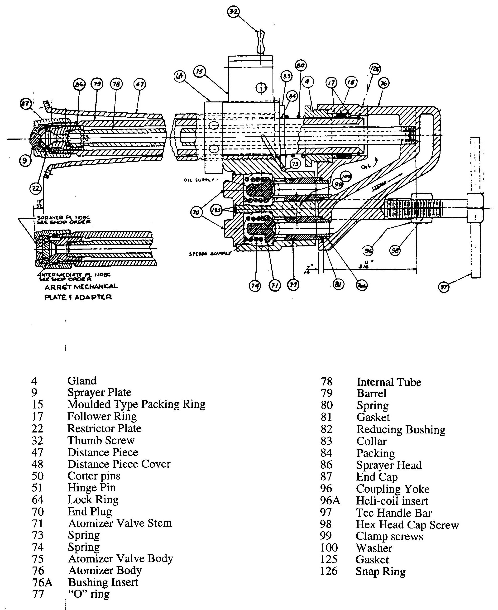
Y-Jet Atomizer
Each boiler is fitted with two gage glasses, high and low water level indicators, a draft gage, exhaust temperature pyrometers, and a smoke periscope to provide necessary operating information to the fireman.
The upper gage glass is of the standard type, while the lower glass is a bicolor type. A bicolor glass operates upon the optical principle of refraction. A beam of light passes through the gage and then through a red or green filter. The different refraction properties of light when passing obliquely through water or steam determines which filter is illuminated. In a bicolor gage glass, water appears green and steam appears red.
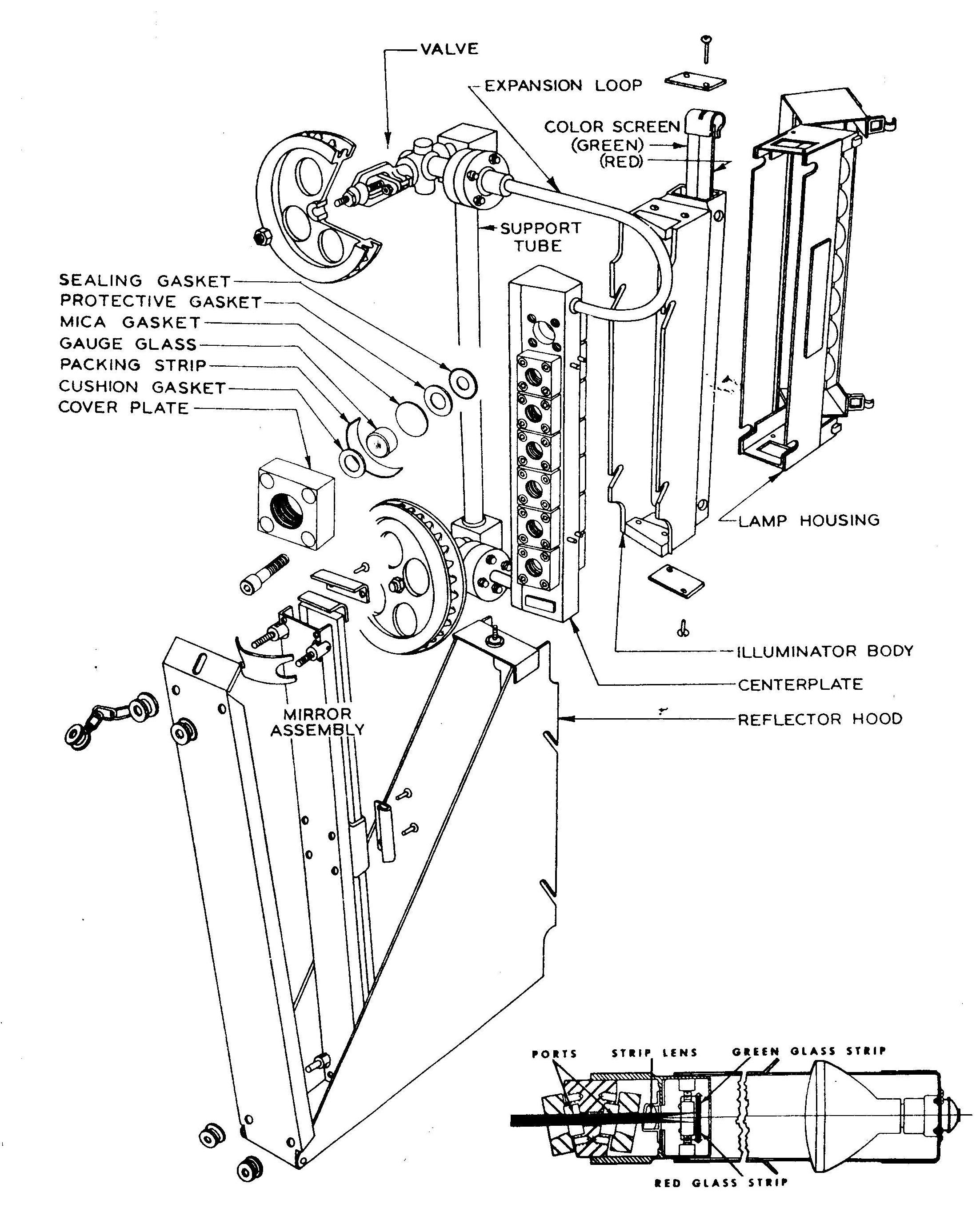
Bi-color Gauge Glass
The smoke periscope is a simple arrangement of mirrors and a light bulb which shines across the uptakes, giving the operator an indication of the opacity of the combustion gasses. It is difficult to destinguish between white and black smoke with the periscope.
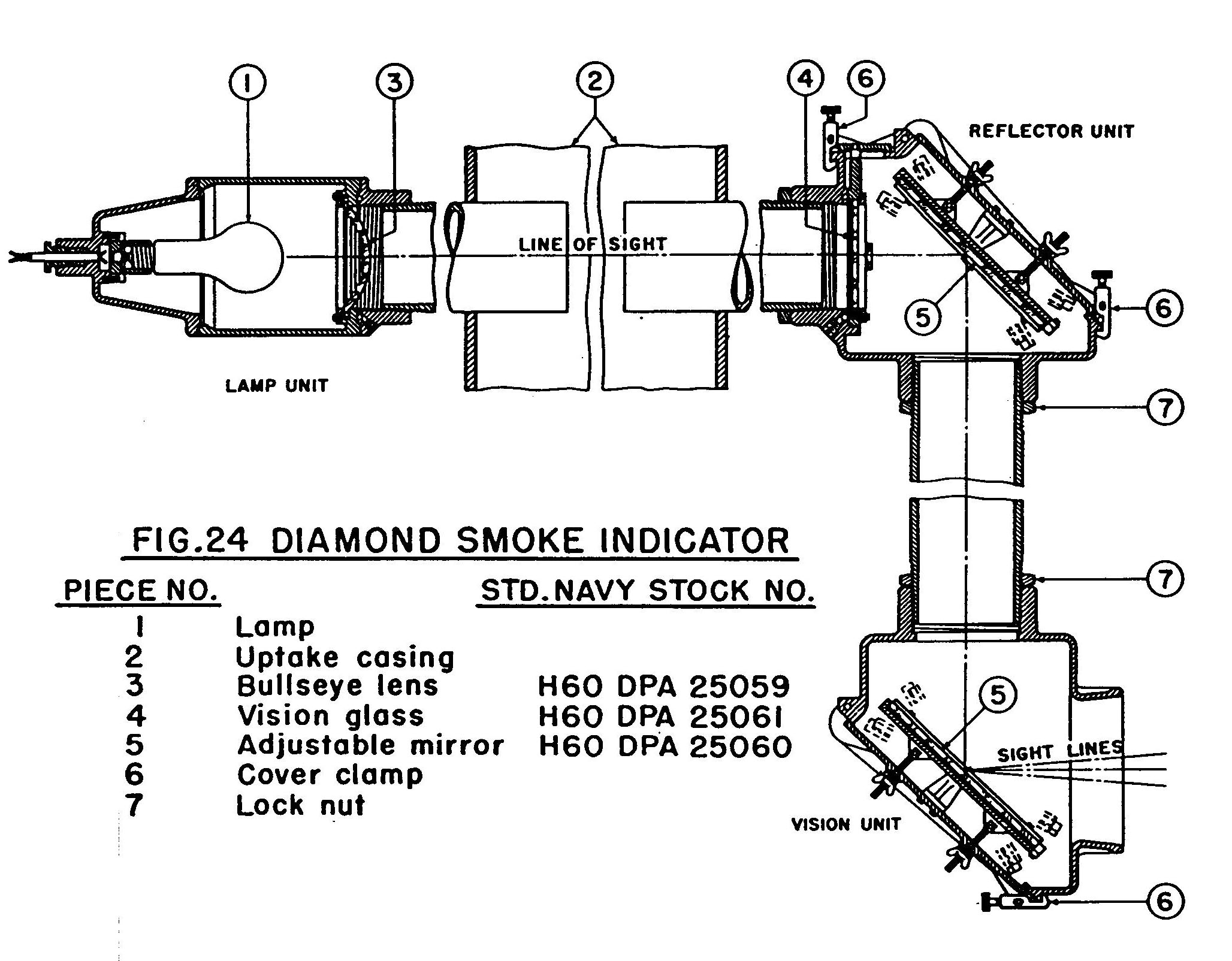
Periscope
Direct comments to William Haynes whaynes@maritime.edu
Mon, Jul 1, 1996
TSPS Engineering Manual ©1995 Massachusetts Maritime Academy