Combustion Control System
Patriot State was the training ship of the Massachusetts Maritime Academy from 1986 to 1998.
The purpose of the combustion control system is to maintain constant steam pressure at the superheater outlet header for all loads by varying the rate of combustion in boiler furnaces. The control also maintains the roper ratio of fuel and air at all rates of combustion.
To change the steaming rate, the automatic combustion control must adjust the following:
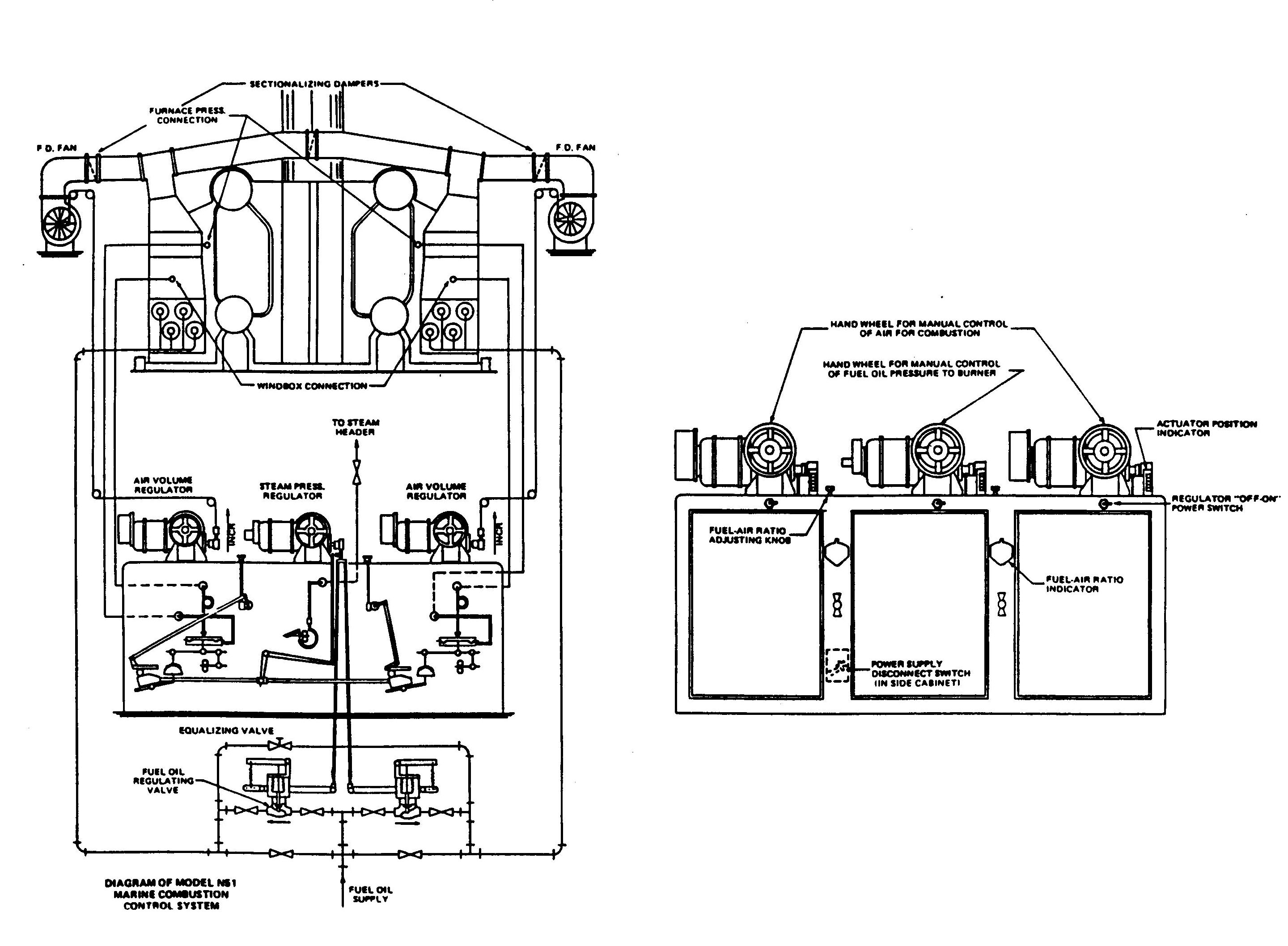
The Marine Combustion Control System consists of three regulators mounted in a single cabinet and three motor driven actuators mounted on top of this cabinet.
The steam pressure regulator controls loading of fuel oil pressure regulating valves and loading of air volume regulators in response to steam pressure variations in the superheater outlet header.
The fuel oil pressure regulating valves automatically regulates fuel oil pressure to burners in direct proportion to the spring loading which is controlled by the steam pressure regulator. Therefore, the position of the steam pressure regulator is directly proportional to fuel oil pressure at the burners and is approximately proportional to quantity of fuel oil being burned.
The air volume regulators control air flow through the burner registers in response to mechanical loading from steam pressure regulators. Ratio of fuel and air to each boiler is adjustable by means of a fuel air ratio knob and indicator for each boiler. The ratio adjusting mechanism is connected in the loading linkage between steam pressure regulator and air volume regulators.
Combustion Control System
Each air volume regulator maintains a balance between mechanical loading from the steam pressure regulator and air flow pressure differential, which is connected to the differential diaphragm of the air volume regulator. The air flow pressure differential is measured across the burner register, hence, no adjustment should be required when burners are taken out or put into service. When a burner is taken out of service, fuel oil is shut off and the air register is closed. Therefore, total air flow to the furnace is proportional to the number of burners in service without changing the relationship between the air flow pressure differential and fuel oil pressure at the burners.
Each regulator is equipped with a separate actuator consisting of a reversible motor which drives the power arm through a double worm gear reducing unit. A handwheel and a disengaging clutch are mounted on the secondary worm shaft at the front of the unit to provide the operator with a self-locking manual control which is instantly available in case of power failure.
A mechanical position indicator is located adjacent to each manual control handwheel to indicate the position of the power arm of each regulator and the equipment being controlled.
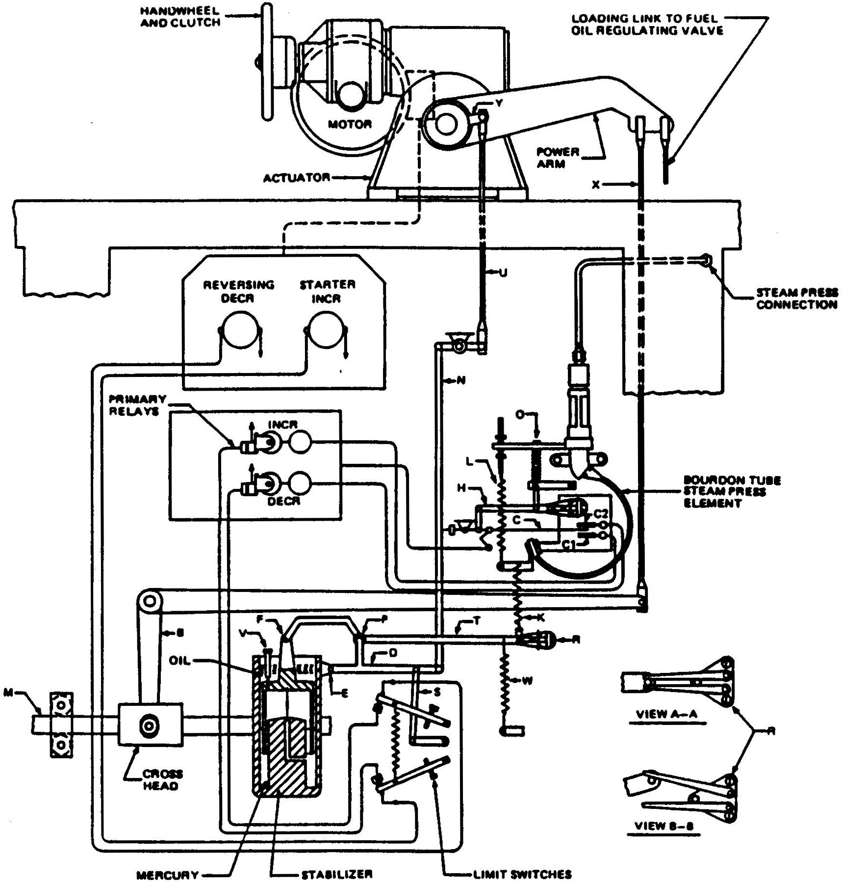
The steam pressure regulator consists of a bourdon tube pressure element, primary contacts, primary relays, stabilizer, and motor driven actuator. The steam pressure regulator serves as a master controller which varies the loading of fuel oil pressure regulating valves and air volume regulators in response to steam pressure variations.
Combustion Control System: Steam Pressure Regulator
The bourdon tube steam pressure element actuates the primary contact finger C between increase and decrease contacts C1 and C2 in response to steam pressure variations in the superheater outlet header. The bourdon tub tip carries the mounting plate for contacts C1 and C2 and the breakaway mechanism which connects with the right hand end of amplifying arm H. Amplifying arm H pivots about the lower end of the link supported by adjusting screw 0, and the left end of arm H connects to center contact finger C. When steam pressure increases, the tip of the bourdon tube moves downward, causing primary contact finger C to make contact with C2 which energizes the decrease primary relay. Contacts of the decrease primary relay energize the decrease coil of the reversing starter through the upper limit switch. Energizing the decrease coil of the reversing starter causes the motor driven actuator to drive the power arm downward to reduce steam pressure.
The action of the stabilizer to prevent over travel for the above operation is as follows:
CAUTION: Shut valves in steam pressure lines connecting bourdon tube pressure element to steam headers, and vent pressure from bourdon tube before hydrostatically testing headers at pressure in excess of normal operating pressure to prevent damage to pressure element.
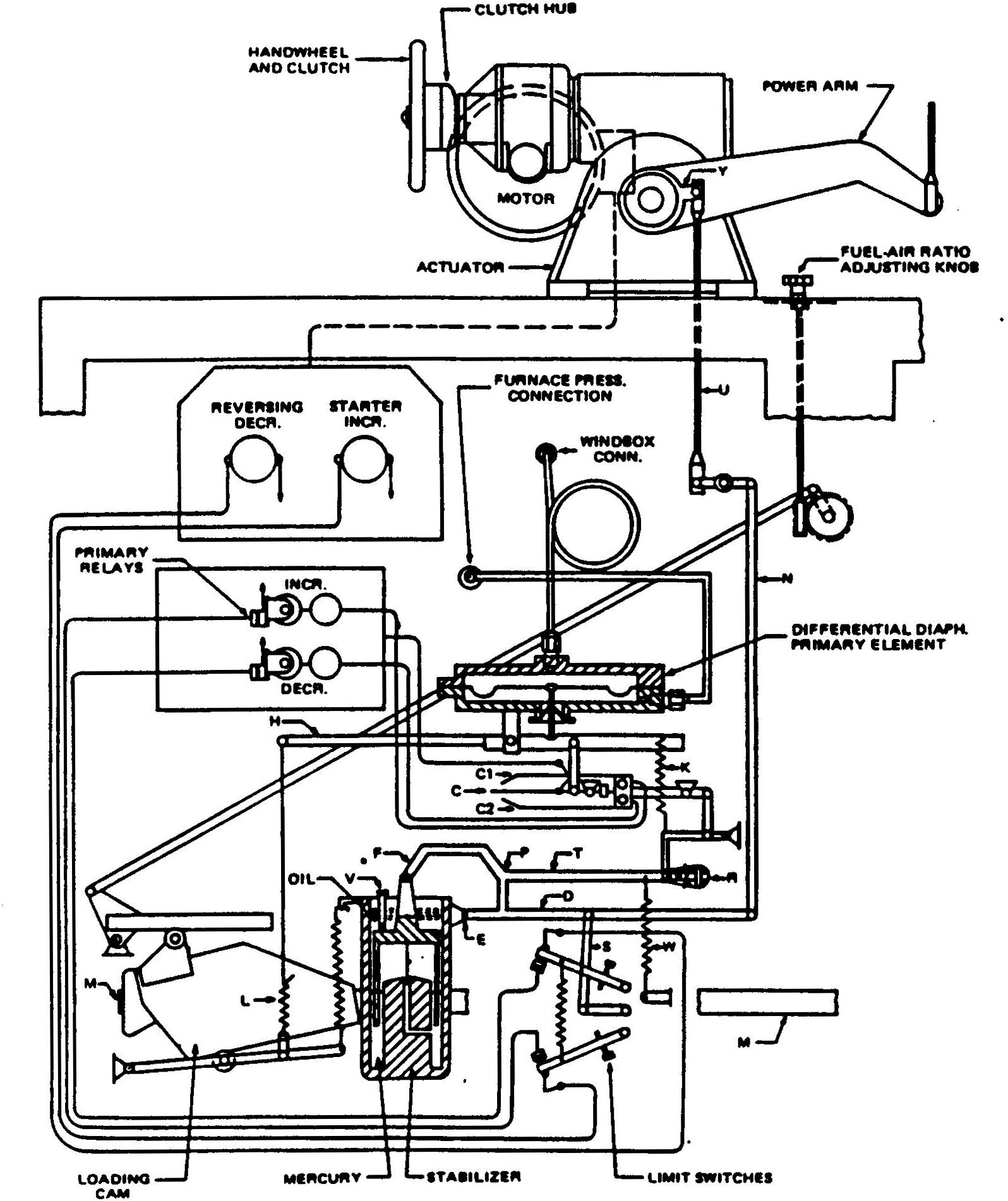
The air volume regulator consists of a mechanically loaded differential pressure diagram element primary contacts, primary relays, stabilizer, and motor driven actuator. The air volume regulator controls air flow through burner registers to maintain a balance between mechanical loading and air flow differential pressure on the differential diaphragm.
Combustion Control System: Air Volume Regulator
The differential diaphragm element is connected to balance beam H, which pivots about point 0, and the left end of beam H is connected to loading springs which are operated by loading cam. The loading cam is operated by the steam pressure regulator. Contact finger C is connected to balance beam H so that any imbalance of the beam causes contact C to make with contact C1 and C2, depending on direction of imbalance. Hence, when loading force on left hand end of beam H is increased, contact finger C makes the contact C2, and air volume regulator decreases air flow so that air flow differential pressure applied to the diaphragm balances decreased loading force. When contact finger C makes with contact C2, the decrease primary relay is energized. Contacts of the decrease primary relay energize the decrease coil of reversing starter through upper limit switch. Energizing the decrease coil of the reversing starter causes motor driven actuator to drive power arm down to reduce air flow.
Action of the stabilizer to prevent over travel for the above operation is as follows:
CAUTION: When blowing out draft lines to windbox and furnace pressure connections, disconnect tubing to the diaphragm chamber so compressed air cannot enter chamber and rupture diaphragm.
The fuel oil ratio linkage connects power arm of the steam pressure regulator with a loading cam for each air volume regulator, and provides an adjustable ratio arm for each air volume regulator to guide loading cams at an angle to produce the desired ratio of air to fuel in each boiler.
The power arm of the steam pressure regulator, which is connected to loading arms of fuel oil pressure regulating valves by ball and socket links BL, is also connected by ball and socket link X to the bell crank which drives shuttle bar M. Loading cams for air volume regulators are connected to each end of the shuttle bar by pantograph linkage so that the cams are free to move in horizontal or vertical planes, but slope of the lower edge of the cam always remains constant in relation to the base of the control cabinet, regardless of the position of the cam in vertical or horizontal planes.
The loading cam of each air volume regulator positions the cam follower arm in proportion to the position of the power arm of the steam pressure regulator, which also positions loading arms of fuel oil pressure regulating valves. Ratio of motion of the cam follower arm to motion of the power arm of the steam pressure regulator is determined by position of the ratio arm. The loading cam is provided with a ratio arm follower which rolls along the lower edge of the ratio arm.
Position of the ratio arm of each air volume regulator is adjusted by a separate fuel air ratio adjusting knob on top of the control cabinet. The adjusting knob positions the ratio arm through a self locking worm and gear. Each worm gear shaft also drives a fuel air ration indicator on front of the control cabinet.
A cam follower spring is hooked in the end of the cam follower arm to keep the loading cam follower in contact with the cam and to keep the ratio arm follower in contact with the ratio arm.
The linear loading spring is connected to a bracket on the cam follower arm and by a wire link to beam H of the differential diaphragm element. Downward pull of the loading spring on beam varies linearly with the position of the cam follower arm. The air volume regulator controls air flow to maintain a balance between air flow differential pressure applied to the differential diaphragm and pull of the loading spring.
A fuel oil pressure regulating valve is supplied for each boiler. This valve is an automatic pressure regulating valve actuated by an internal bellows. The bellows receives its power from fuel oil pressure, therefore no external source of power is required. This valve regulates fuel oil pressure to burners in proportion to the position of the loading arm. Each valve can be adjusted so that the minimum pressure for which it will control is sufficiently high to prevent loss of ignition. The valve is equipped with compensating springs which compensate for the characteristic of the loading springs, so that fuel oil pressure to burners will be maintained at a constant value corresponding to the position of the loading arm, regardless of quantity of fuel oil being burned or number of burners in service.
When putting boilers into service, manually control fuel oil pressure by the handwheel of the steam pressure regulator and manually control air to each boiler by the handwheels of the air volume regulators.
When steam pressure has been raised to operating pressure, approximately 600 psi, the steam pressure regulator can be put into service. To put regulator into service, turn Power switch (under handwheel) for regulator control circuits to ON position and allow about a minute for the primary relay vacuum tube temperature to rise. If air flow differential pressure on the diaphragm does not exactly balance loading from the steam pressure regulator, the clutch hub which is driven by the actuator motor will begin to turn. If clutch hub turns in a clockwise direction, this indicated that loading is greater than air flow differential pressure. Turn fuel air ratio knob in the direction to move the fuel air ratio indicator to the left until regulator is balanced and clutch hub will stop turning. If clutch hub turns in counterclockwise direction, fuel oil ratio indicator should be moved to the right until clutch hub stops turning. When clutch hub stops turning, this indicates that balance beam is in balance and that primary contacts are open. The clutch of the actuator can then be engaged by pushing the handwheel inward and the regulator is in automatic operation.
When air volume regulators are in automatic operation, fuel air ratio can be adjusted to correct the CO2 for varying burner conditions and for different size burner tips, by turning the fuel air ratio knob. The fuel air ratio indicator is moved to the right to increase air and to the left to decrease air.
Any one or all of the regulators can be taken out of service by turning the power switch for regulator control circuits to the OFF position. Then manual control is available by pulling out on the handwheel to disengage the clutch.
When variable speed forced draft fans are used, fans should be transferred to high speed when air volume regulators approach the wide open position, and fans may be transferred back to low speed when boiler load is reduced to the point where low fan speed will provide the required air for proper combustion.
If inlet vanes are used on forced draft fans, vane linkage must be properly maintained to prevent development of lost motion.
Direct comments to William Haynes whaynes@maritime.edu
Mon, Jul 1, 1996
TSPS Engineering Manual ©1995 Massachusetts Maritime Academy