Ship's Service and Cargo Refrigeration Units
Patriot State was the training ship of the Massachusetts Maritime Academy from 1986 to 1998.
The ship's stores refrigeration plant is served by two compressors located in the engine room.
The ship's stores plant aft is the direct expansion type and uses Freon-12 as the refrigerant. Each of the compressor units has a capacity of 8.55 tons at -15° F. suction temperature and 105° F. condensing temperature. The plant supplies liquid refrigerant to the evaporators to maintain the refrigerated spaces listed below at the temperature indicated.
Compartment     Temperature    Type of Evap.   Quantity
Fish room           0° F.         Finned coils       57 sq.ft. surface
Meat room           0° F.         Finned coils       739 sq.ft. surface
Frozen foods        0° F.         Finned coils       303 sq.ft. surface
Dairy room          32° F.        Cold diffuser      1
Fruits & veg. rm.   32° F.        Cold diffuser      2
Potato room         45° F.        Cold diffuser      1
Cheese room         40° F.        Cold diffuser      1
The plant also provides refrigeration for two service box brine coolers, two ice water coolers, and may be used to serve the auxiliary water chiller.
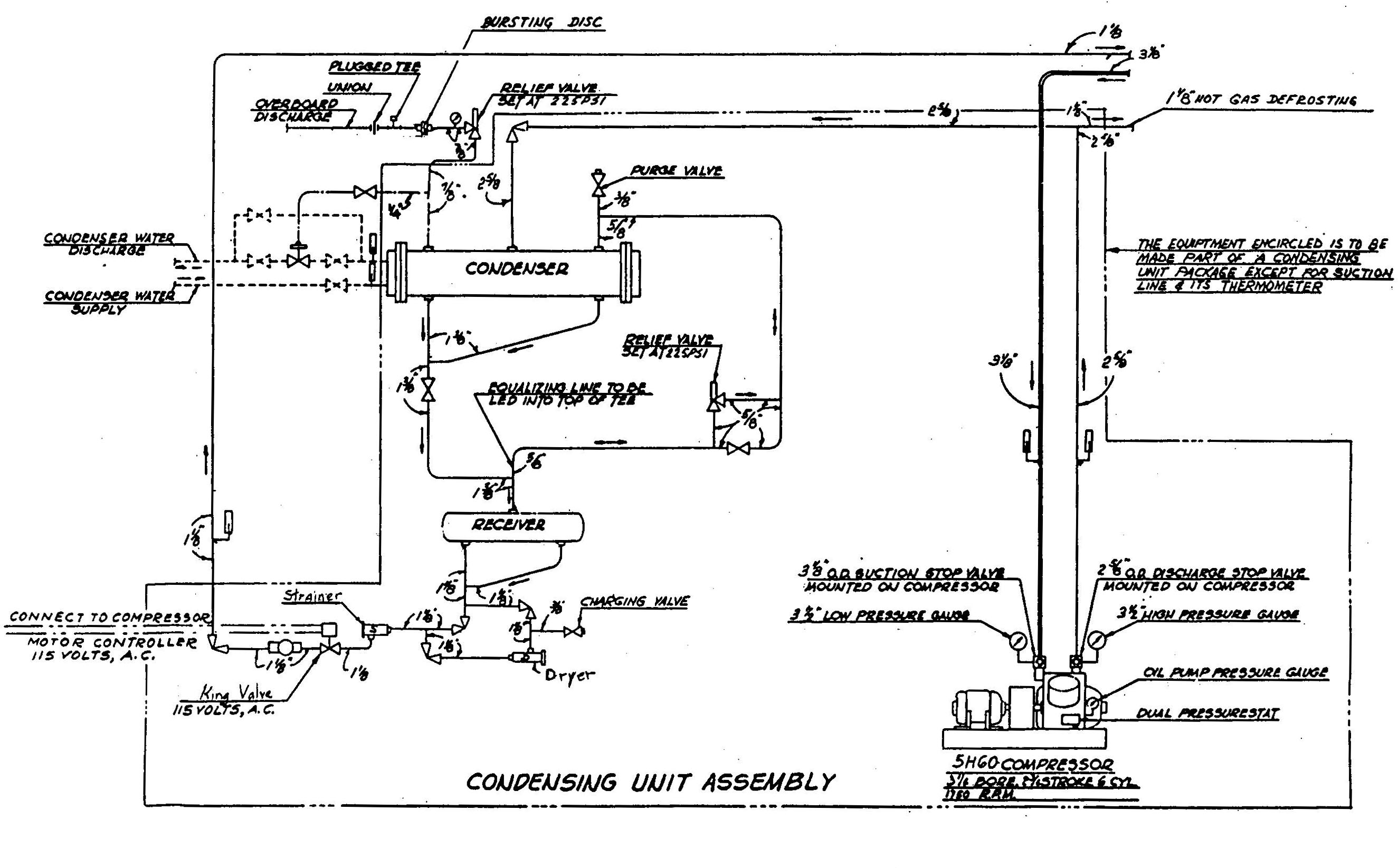
The ship's stores plant consists of two compressor units inter-connected. One compressor can handle the entire load with the other compressor remaining as standby or, if necessary, being using to operate the auxiliary water chiller. Hot gas defrosting is provided for the coils in the 0° F. compartments. The entire plant requires a charge of approximately 434 lbs. of Freon-12 for proper operation.
The service box brine coolers supply the following service boxes with brine which is a 30% by volume solution of propylene glycol with a freezing point at +7° F. All these boxes are maintained at 40° F. using pipe coils.
Service  Volume
Officer's mess  14.5 cu.ft.
Crew's mess 14.5 cu.ft.
Crew's pantry   14.5 cu.ft.
Dispensary  4.0 cu. ft.
Club bar box    1.0 cu. ft.
This ship's cargo reefer system located on the forecastle deck is identical to the ship's store plant except that it uses glycol for condenser cooling. These units supply R-12 to two evaporator coils located on either side of the machinery space. Each box can be used as a chill or a freeze box since each has two TEV's (one 32° and one 0°).
The auxiliary water chiller can be used with either brine or water and it may supply the air conditioning system under low load conditions or the cargo refrigeration plant condenser. The brine solution for this service is a 20% by volume propylene glycol solution with a freezing point of +19° F. The chiller is a shell and tube heat exchanger with water or brine flow through the shell and refrigerant through the tubes. It will cool 300 gpm of propylene glycol from 47° F. to 45° F. with an evaporating temperature of 37.5° F. The chiller cools the glycol for use as a cooling medium in the forward reefer units.
The low temperature (0° F) compartments are provided with a wall type direct expansion cooling coils. The coils are constructed of 1-1/4" O.D. seamless steel tubing of .083" wall thickness with 5" wide x .025" thick steel fins. The higher temperature compartments are provided with ceiling suspended type cold diffusers which contain a direct expansion cooling coil constructed of copper finned tubing enclosed in a galvanized casing with a drip pan. Each cold air diffuser has a propeller type fan mounted at the rear of the unit.
The chilled water system supplies ice cold water to all of the older scuttlebutt located around the ship as well as to rooms on the bridge, sun an "A" deck. The system is a closed loop. Water from the potable water system is either pumped directly into the system, or is directed to an insulated cooler located on the refrigeration flat, port side. After the water has passed through the cooler and it mixes with the returning water from a recirculating pump; it is then discharged throughout the ship.
The potable water to the cooler can be cooled from 90° F. to 50° F. with a 50 gph output from the cooler. The cooler itself uses Freon (R-12) mainly to cool the walk-in on "B" deck. From the main refrigeration system, liquid Freon may go through a hand expansion valve to the cooler. It may also pass through a liquid line dryer, an electrically operated solenoid, which senses cooler outlet temperature, and finally to the thermostatic expansion valve to the cooler. After the Freon has cooled the water, it passes through a back pressure regulator and continues back to the main system.
Water which doesn't go to the cooler, but instead goes to the recirculating pump, isn't as cool as water from the cooler. When mixed, it is referred to as ice water. The pump is a single stage centrifugal pump that can produce 25 gpm.
Ship's Service and Cargo Refrigeration Units
Each of the four compressors serving the ship's stores and cargo plants is a reciprocating, single acting unit, direct driven by a 40 H.P., 440 volt, 3 phase, 60 cycle General Electric Motor. The compressor has a cast iron crankcase and is provided with a structural steel base.
The compressors have the following features:
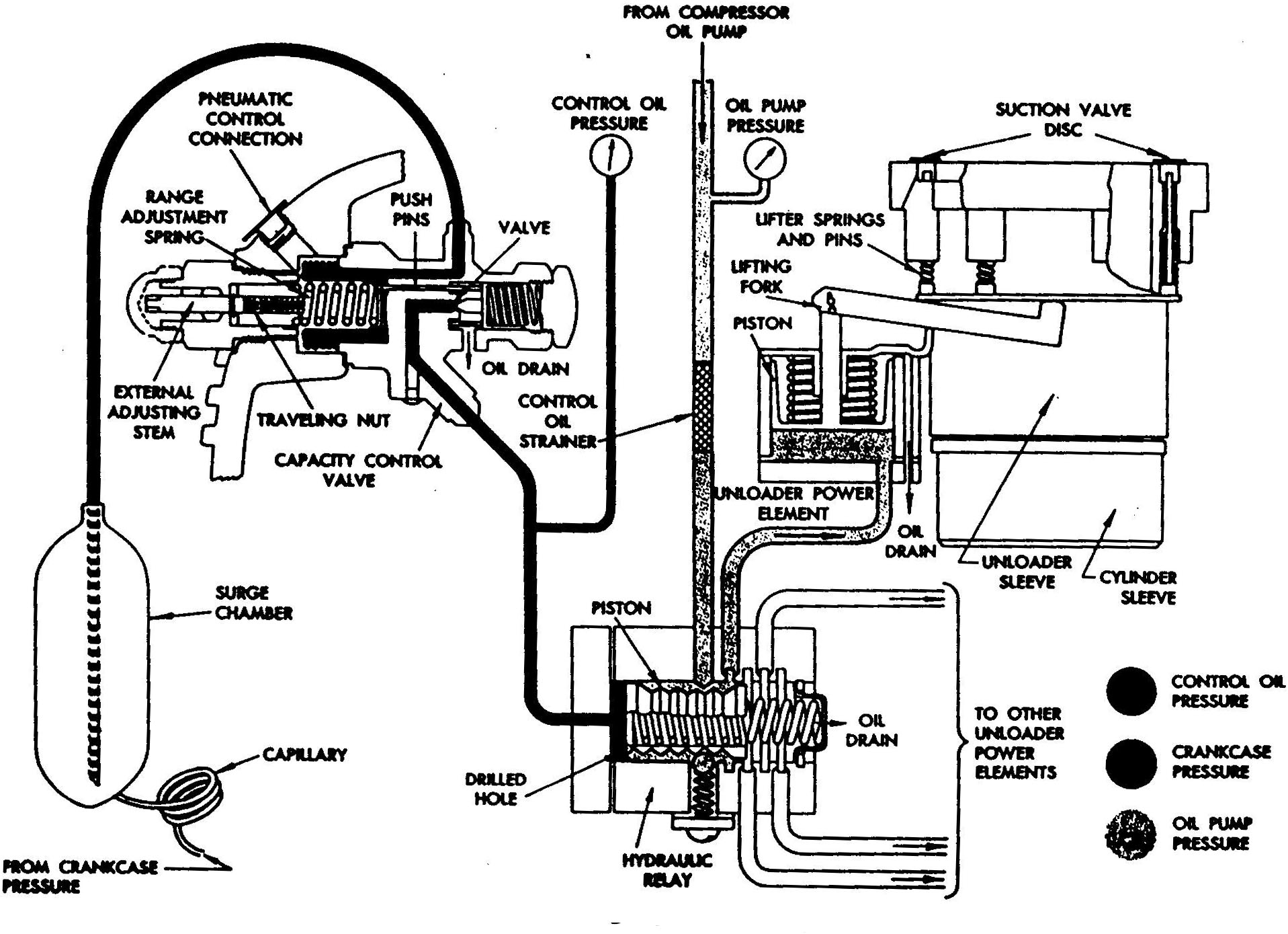
Compressor Unloading System
Compressor Specifications
 Cylinders      6
 Stroke         2-3/4"
 Bore           3-1/4"
 Speed          1750 RPM
 Model          SH60
 Capacity       8.55 tons at  -15° suction temperature and
                105° F. condensing temperature
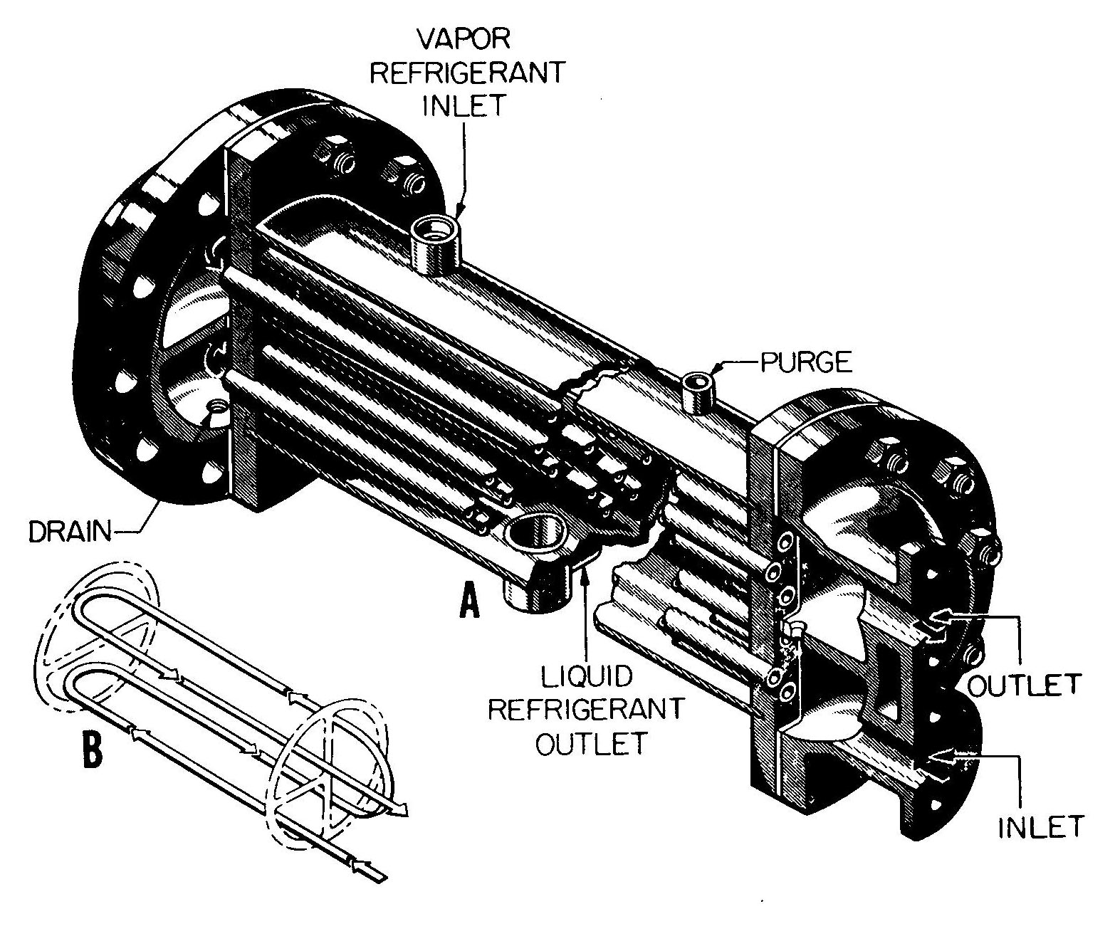
The condensers are of the multipass shell and finned tube type with circulating water flowing through the finned tubes. The refrigerant vapor is admitting to the shell and condenses on the outer surface of the finned tubes. The condenser is constructed of a steel shell with copper nickel tubes and tube sheets and gun metal waterheads.
Sea water flow is regulated by a water regulating valve which senses the condensing pressure. The condenser water regulating valve should be set to maintain a condensing pressure of approximately 125 psig.
Condenser Specifications Shell diameters 12-3/4 O.D. Overall length 77-9/16" Number of tubes 118 Tube size 3/4" O.D. x .049" wall Effective cooling surface 280 sq.ft. Cooling sea water quantity 190 gpm Number passes 2 Manufacturer's model number 9W100-129
Refrigeration Condenser
The receiver consists of a steel shell with dished heads welded at each end. It collects the liquid refrigerant draining from the condenser. The shell is provided with one refrigerant inlet and two outlet connections and a magnetic float type indicator for determining the liquid level.
Receiver Specifications
 Refrigerant capacity            285 lbs.
 Shell diameter                  14"
 Overall length                  44-3/8"
 Type mounting                   Horizontal
 Manufacturer's assembly number  8M35-114
A heat interchanger is installed in the main suction and liquid lines leading from the compressors to the cooling coils and cold diffusers. Suction gas circulates through the tubes of the heat exchanger while liquid refrigerant passes through the shell. The cold suction gas cools the warm liquid refrigerant, thus, increasing the efficiency and capacity of the system. A bypass valve is provided in the liquid line to the interchanger. These are only on the forward units.
The thermal expansion valves control the quantity of liquid refrigerant that passes to each refrigerant circuit within the cooling coils. They are designed to maintain a constant °ee of superheat in the refrigerant gas leaving the cooling cools regardless of suction pressure. Thus, their dual function is; automatic expansion control and prevention of liquid refrigerant from surging back to the compressor.
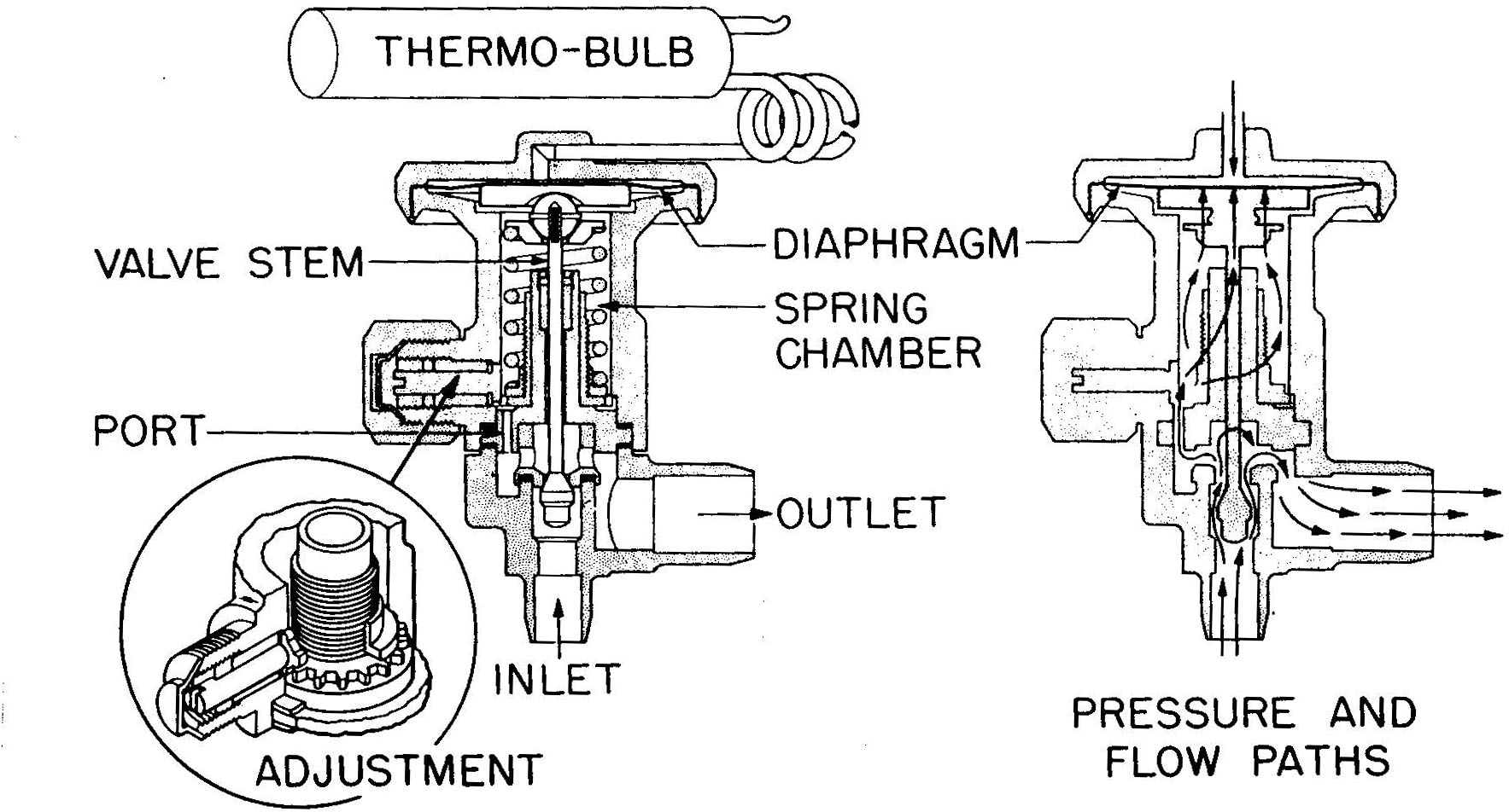
Thermal Expansion Valve (TEV)
The solenoid stop valves, actuated by temperature control switches, cut off the supply of liquid refrigerant to the thermal expansion valves when the desired temperature is reached in the space or medium being cooled.
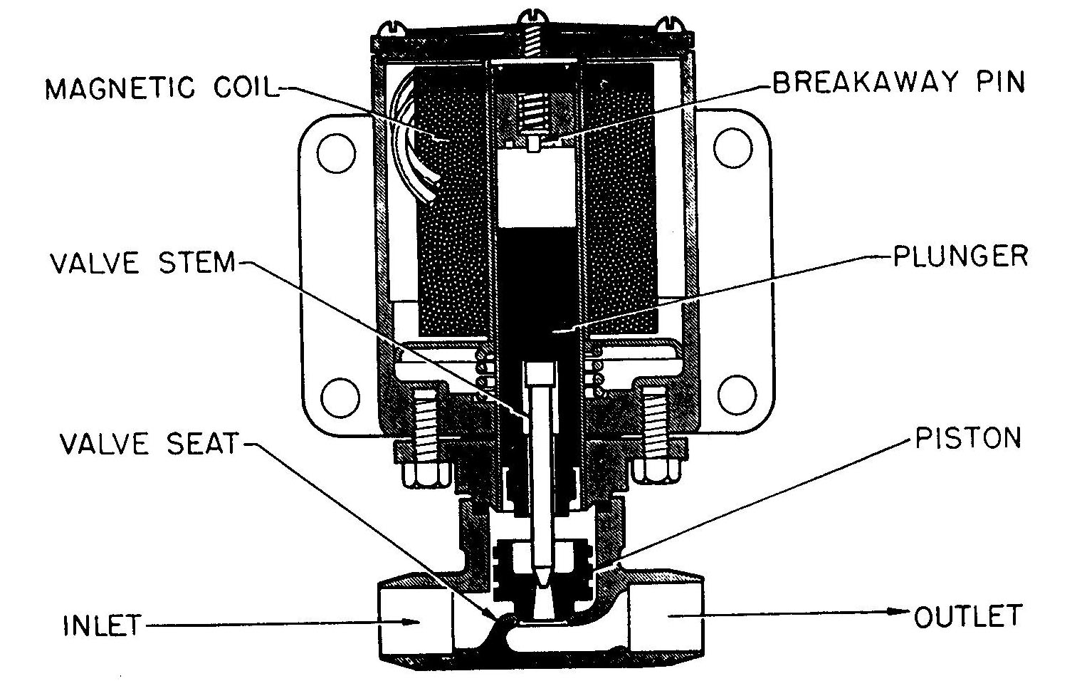
Solenoid Valve
The high pressure control stops the compressor in the event of excessive pressure in the high side of the system and permits the compressor to be started again when the pressure drops to the cut-in setting of the high pressure control (by pushing the controller start button). The low pressure control stops and starts the compressor at the proper predetermined suction pressures. These two controls are contained in one switch box called the dual pressurestat.
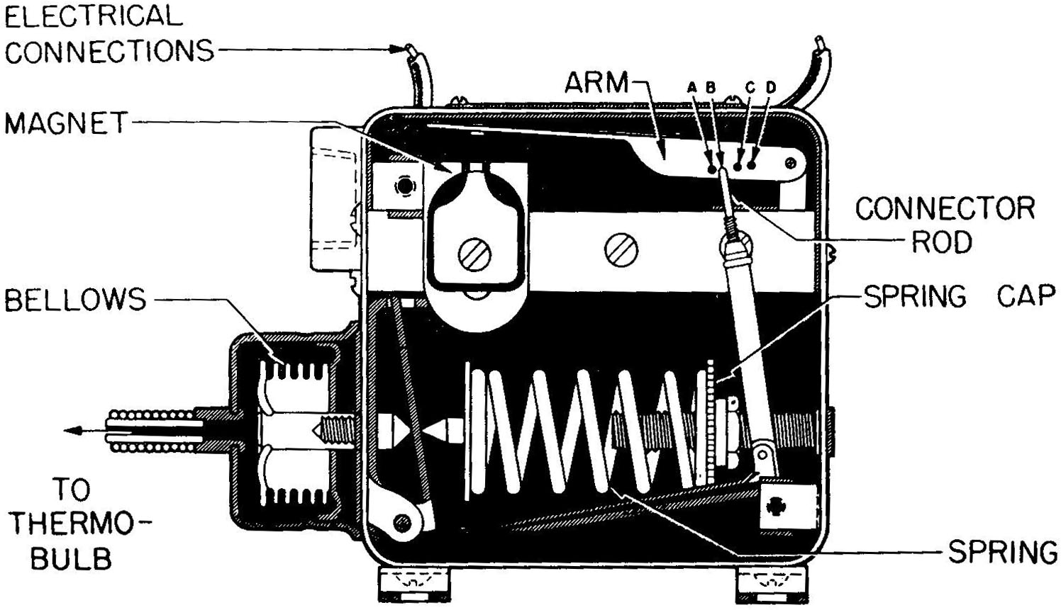
Pressure Switch
Water regulating valves automatically control the amount of water flow through the condenser, thus maintaining constant condensing temperatures (and high side pressure). There is a strainer screen located within the regulator that must be periodically serviced to insure proper operation.
Since Freon-12 is capable of loosening and removing all particles of dirt and scale, liquid line, suction line and oil strainers are employed throughout the plant.
The system is fitted with a liquid line dryer consisting of a cylinder and renewable cartridges filled with activated alumina or silca gel. This dryer is to be used only when charging refrigerant or for freezing the system of moisture. If the system is properly purged and dehydrated when first installed and then operated with caution, it will be necessary to use the dryer only when charging.
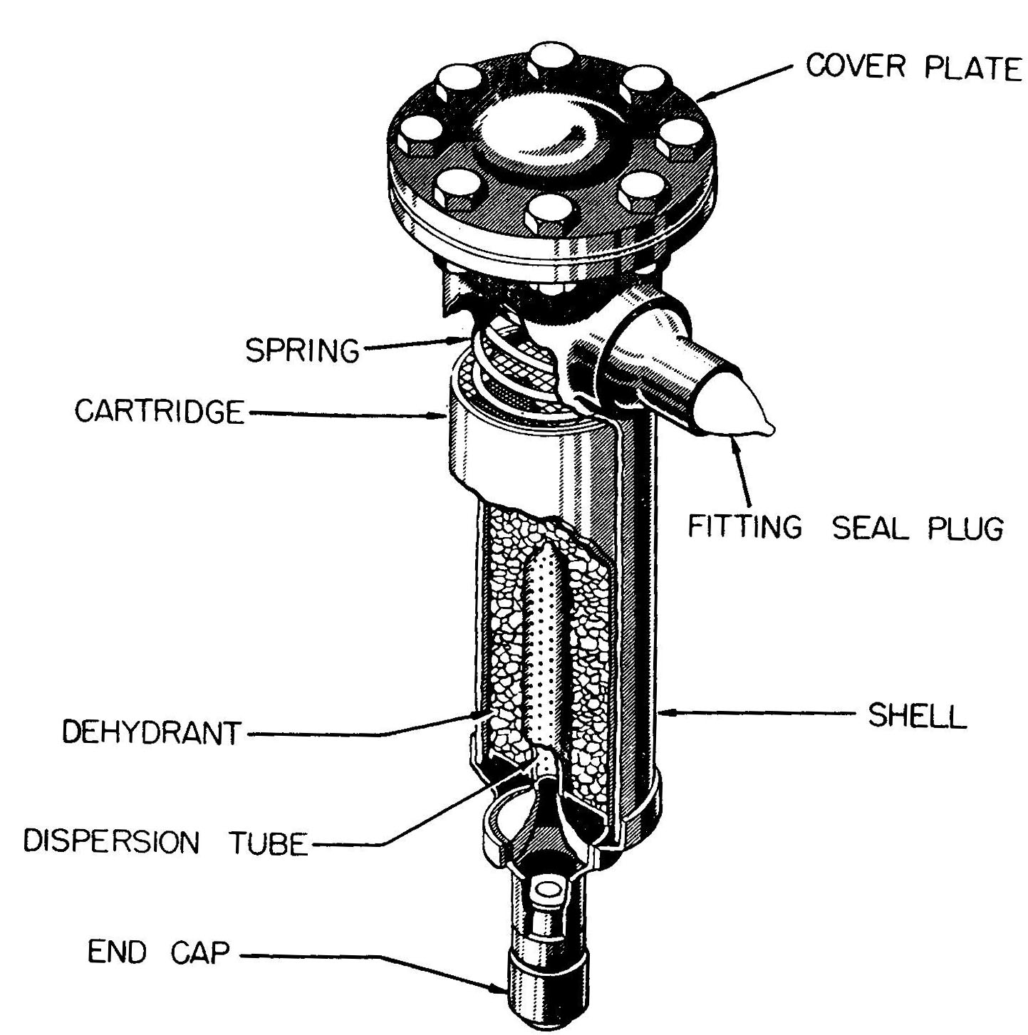
Dryer
A hand expansion valve which by-pass the liquid strainer, solenoid valve and thermal expansion valve is provided for each refrigerant circuit. This valve can be used whenever any of these parts are shut down for service or repair. The hand expansion valve must be carefully throttled to supply sufficient refrigerant to the cooling coil without flooding liquid refrigerant back to the compressor.
The suction pressure regulating valves are used in the suction line returning from the evaporator in the refrigerated compartment. This prevents an excessive difference between compartment temperature and the refrigerant temperature in the cooling coil. A gauge connection is provided on each regulator for use in adjusting. By-pass valves are provided so that the regulators can be cut-out of the circuit during initial temperature pull down or low temperature operation.
Direct comments to William Haynes whaynes@maritime.edu
Mon, Jul 1, 1996
TSPS Engineering Manual ©1995 Massachusetts Maritime Academy