York Unit: Refrigeration Cycle
Patriot State was the training ship of the Massachusetts Maritime Academy from 1986 to 1998.
All of the air conditioning for the different spaces on board the Patriot State begins in the engine room. There are three refrigeration units: one steam (600 psi), one electric (both are Carrier units and are located in the engine room), and one York electric unit (located on "B" deck aft of the port side fueling port). These units use Freon-11. The function of these units is to cool down a solution of glycol, the secondary refrigerant, to a set temperature. The glycol is then pumped throughout the ship.
After the glycol leaves the engine space, it is pumped to ten fan rooms (four in the superstructure and six in the cadet berthing areas) around the ship. The remaining fan rooms have been deleted from the system. Located inside each of the four fan rooms in the superstructure is a control panel. This panel works in conjunction with the thermostats located in each room and passageways within the ship. Also, at least one, if not two, sources of fresh incoming air are supplied to each room.
As the incoming or return air enters the duct work, it passes over a steam (35 psi) preheat coil. On the down stream side of the coil, is a thermostat sensing bulb. If the air temperature is lower than 50° F., it transmits a signal to an air operated valve to open and allow steam to flow through the coil to warm the air. This occurs prior to the air passing through the fan. The same process occurs on the discharge side of the fan.
The cooling coil is located just before the fan. This also has an air operated valve which allows the glycol to the coil. A thermostat with a sensing bulb is down stream of the coil. This alone does not operate the valve. A humidifier which measures the amount of humidity in the air also acts to operate the valve. The cooling coil transmits an air signal agreed with the thermostat setting. The glycol doesn't enter the coil. It continues on its way by-passing the coil and either passes into a coil needing the coolant or is discharged back to be cooled again. If the temperature of the space served by the coil is too high, an air signal is sent to open the valve allowing the glycol to enter the coil.
York Unit: Refrigeration Cycle
The fan rooms in the cadet berthing areas differ slightly. Electric thermostats are utilized instead of air operated ones. They are electrically connected to solenoid valves for the cooling coil or to the reheat coils in duck work. These thermostats work in a similar manner to the ones in the superstructure fan rooms.
The glycol system is designed to use refrigerant R-11 to remove heat from a glycol water solution. The glycol water solution is then circulated as a secondary refrigerant to the fan room compartments of the ship.
Heat from the spaces being cooled is absorbed by the circulating glycol/water solution when air passes over fan room cooling coils. This heat is removed from the solution by the primary refrigerant R-11 in the glycol chiller units.
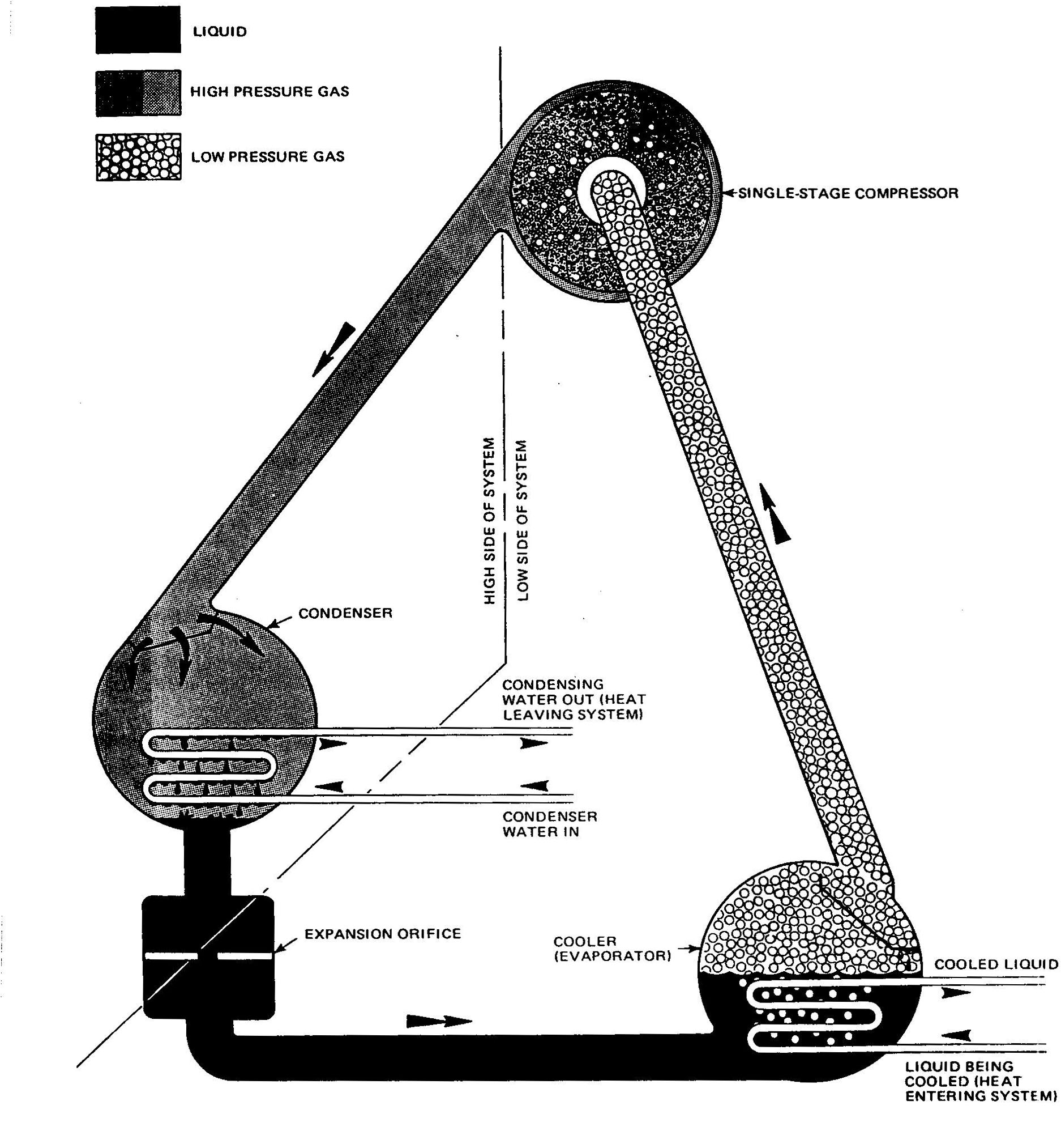
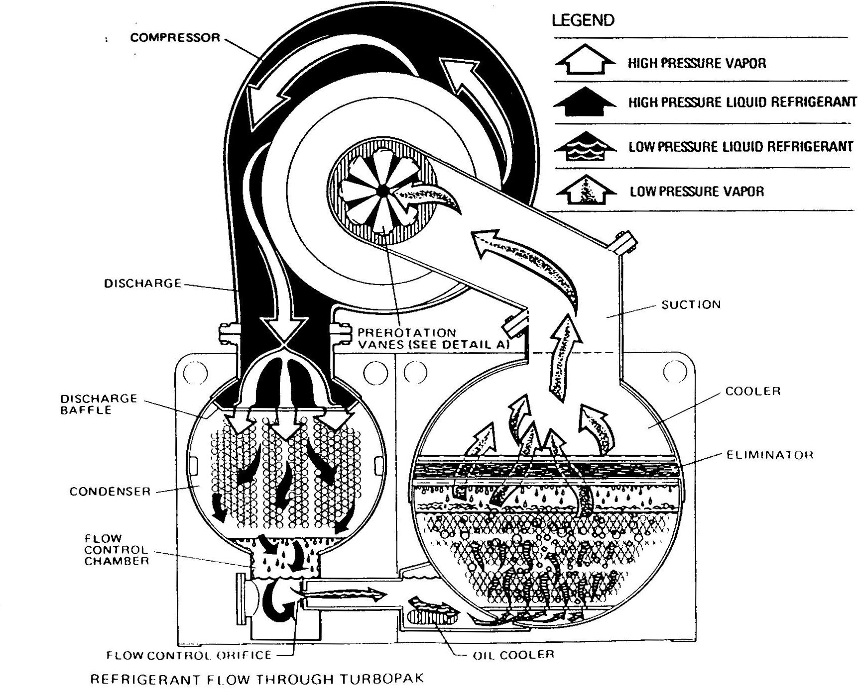
The system cycles as follows:
Refrigerant R-11 vapor is drawn from the evaporator or cooler to the compressor where, through compression, it changes from a low temperature, low pressure vapor to a high temperature, high pressure vapor.
The refrigerant R-11 is then discharged to the condenser as a high temperature, high pressure vapor. In the condenser R-11 vapor condenses, giving up its superheat, its latent heat, and its latent heat of compression, to the sea water that flows through the condenser tubes and overboard
The liquid refrigerant R-11 then passes through a high pressure float metering device and enters the cooler.
Inside the cooler, heat is transferred from the glycol returning from the air conditioned spaces, to the liquid refrigerant. As the heat is transferred, the liquid refrigerant absorbs its latent heat of vaporization, boils, and vaporizes.
The chilled glycol water is recirculated back to the fan room coils and the vaporized refrigerant is drawn into the compressor. The cycle of events is repeated until designed cooling is accomplished.
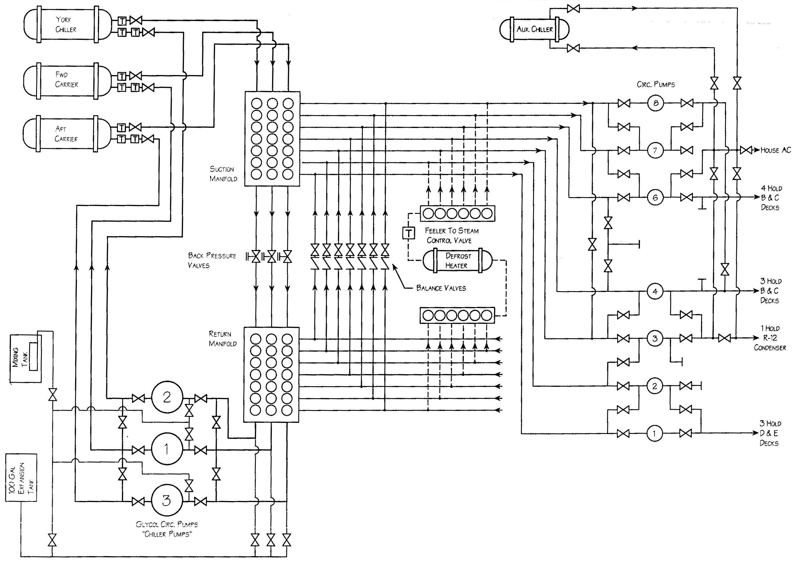
Glycol Distribution System
The glycol system on board utilizes three R-11 chiller units, three salt water circulation pumps, three main glycol circulation pumps, and seven glycol supply pumps.
Heated glycol returning from air conditioned spaces (via return headers) all feed into a common return manifold. Three glycol circulation pumps take suction from this manifold and discharge the glycol into the R-11 chiller units. After its heat is removed in the chiller units, the glycol is discharged into the suction manifold that supplies the 7 glycol circulation pumps. The 7 individual glycol supply pumps discharge chilled glycol to the ships air conditioning and refrigeration spaces.
After removing heat from the ship's air conditioning spaces, the heated glycol returns to the suction manifold in the engine room and the cycle of events repeats.
The Patriot State is equipped with three operable HVAC R-11 centrifugal chiller units: two Carrier model 17 PB52 (one steam driven, one motor driven) and one York model 0TC3C3C2 IMBS (motor driven) unit.
The three stage centrifugal compressor employing Freon 11 refrigerant is driven by a direct-connected steam turbine. The compressor's capacity can be controlled by variation of the steam turbine speed, positioning of the hot gas bypass valve, or throttling of the suction dampers.
Capacity            450 tons at 35° F. suction temperature
                    and 111° F. condensing temperature
Compressor Speed    4,540 RPM
Brake Horsepower    490 bhp
Number of Stages    3
The unit is a three stage centrifugal compressor driven by a three phase Siemens-Allis induction motor. The motor is directly coupled to the compressor.
Capacity                450 tons at 35° F. suction temperature
                        and 111° F. condensing temperature
Compressor Max Speed    4,540 RPM
Brake Horsepower        490 bhp
Number of Stages        3
Motor Data
    H.P.                600
    Amperage            651
    RPM                 3,545
Because this unit's prime mover is an a.c. motor, capacity of the unit cannot be controlled by compressor speed. Thus, unit capacity is controlled by the hot gas bypass or by throttling of the suction dampers.
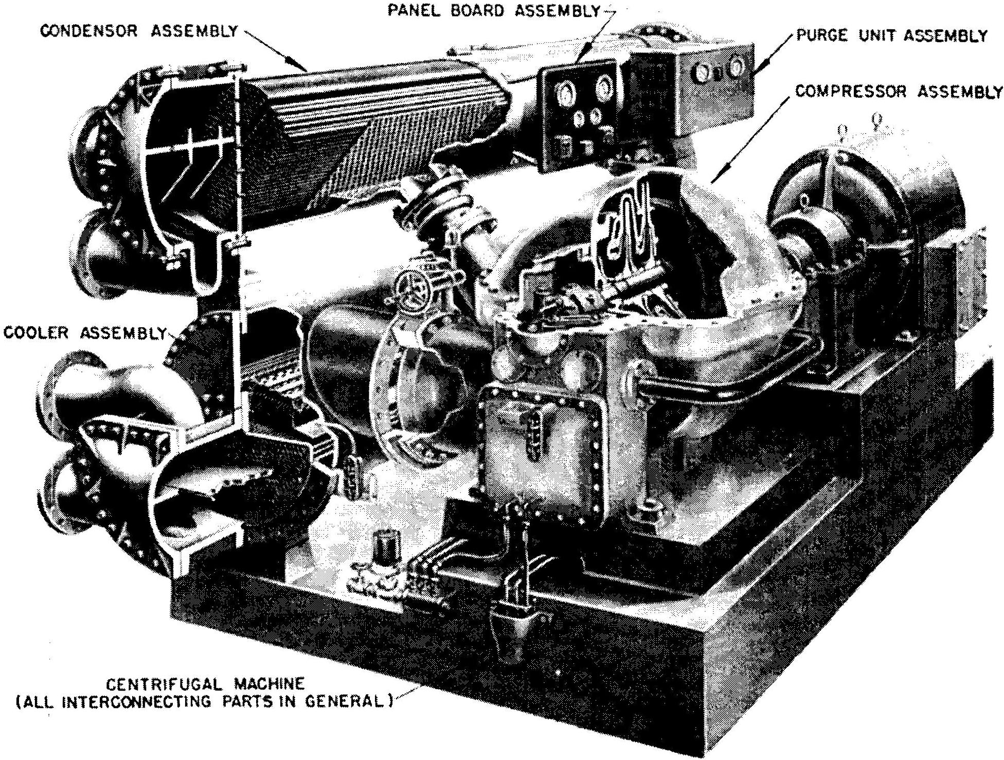
Carrier Centrifugal Compressor
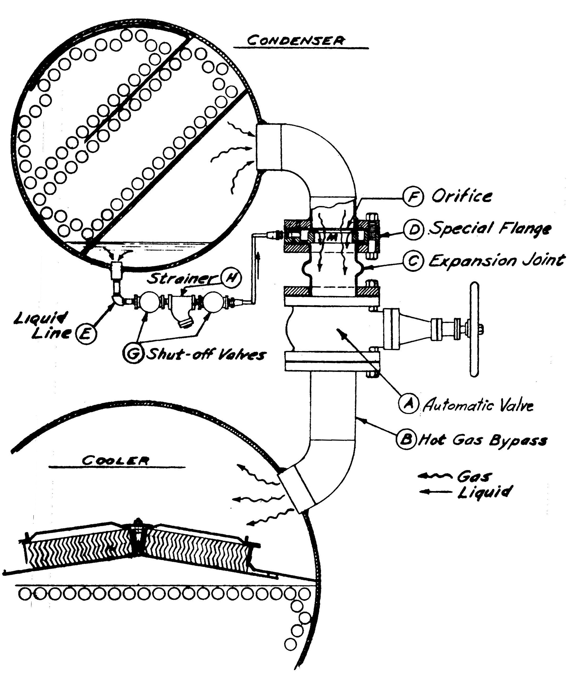
Carrier Unit: Hot Gas Bypass
The York unit is a single stage compressor with a prime mover that is a direct coupled, three phase, Reliance A.C. motor. The unit's capacity is controlled by the hot gas bypass or by throttling the suction dampers.
Capacity                321 tons at 31 °F,
                        suction pressure 18.34 "Hg,
                        Discharge 13.09 psig
Compressor              York model LTH95, single stage, open
Compressor Speed        8,236 RPM
Refrigerant Charge      850 lbs.
Motor Data
    H.P.                385
    Amperage            425 (full load)
    RPM                 3570 (full load)
The York Turbopak is designed to use less power by taking advantage of lower than design temperatures that are naturally produced by cooling towers throughout the operating year. Exact control of condenser water such as a cooling tower by-pass, is not necessary for most installations. The Turbopak requires only that the minimum condenser water temperature be no lower than shown in Fig. 5, for proper and efficient operation. At start-up the entering condenser water temperature may be as much as 25° F. colder than the standby return chilled temperature. Cooling tower fan cycling will normally provide adequate control of the entering condenser water temperature on most installations.
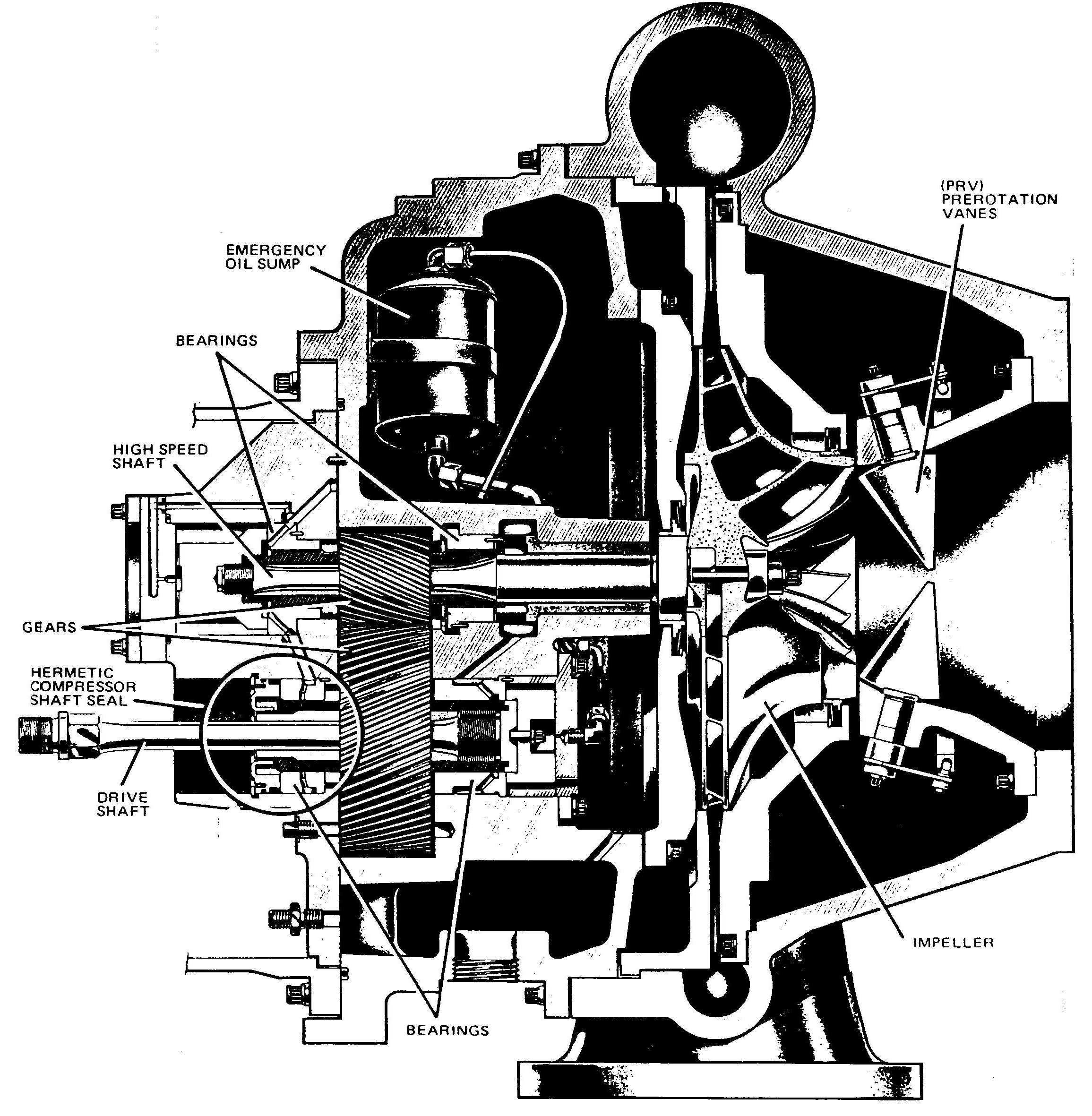
York Centrifugal Compressor
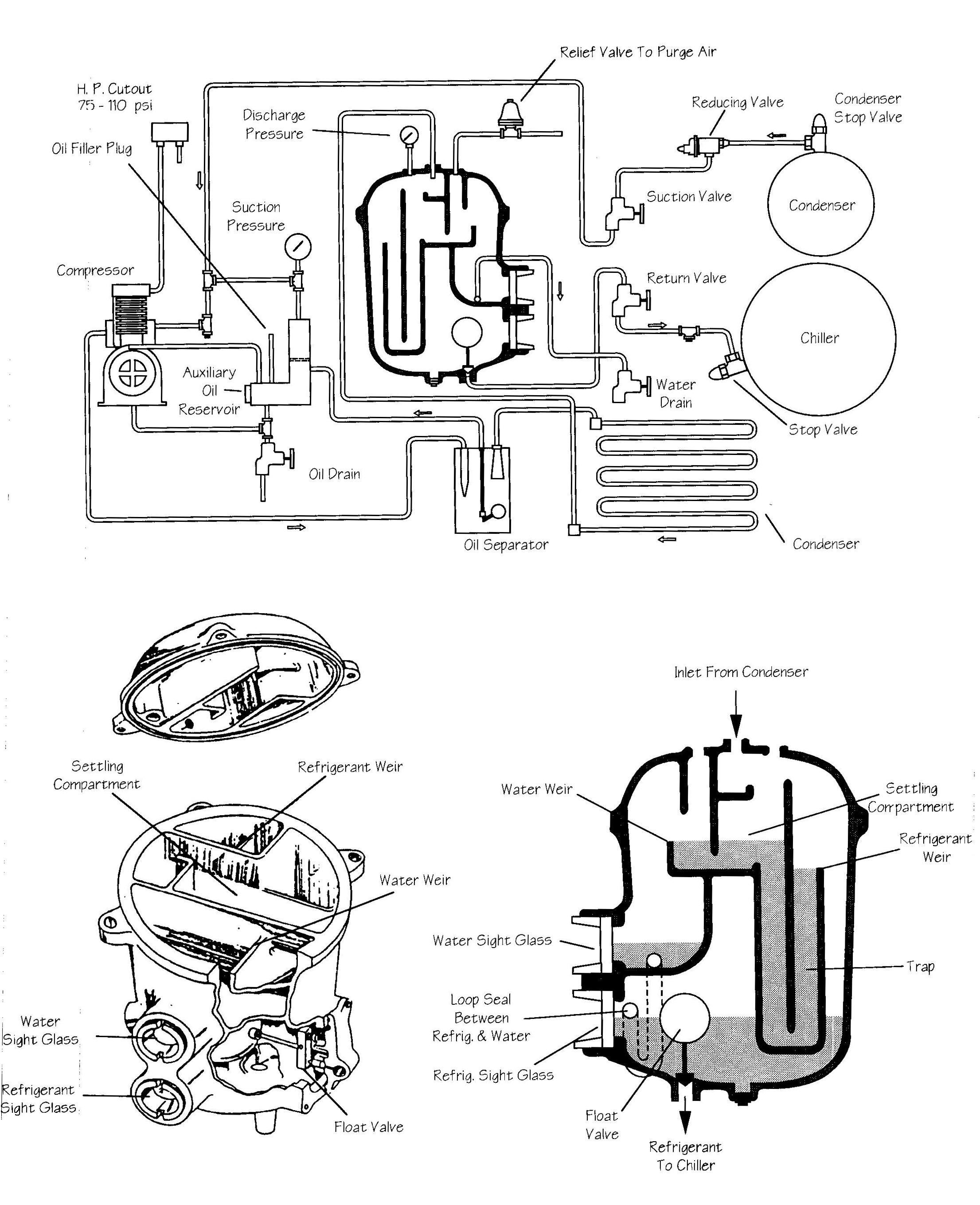
York Unit: Schematic
An increase in head pressure in the condenser (all other conditions of load, speed, temperature, etc., remaining uniform) indicates the presence of air. Observation of the difference between outgoing condenser water temperature and the temperature shown on the condenser gauge may also be useful in determining the presence of air. An increase in this difference under the same circumstances as outlined above may be caused by air. Similarly, an increase in the cooler pressure (for decrease in the vacuum) over the pressure corresponding to the cooler temperature, during operation, may be caused by air.
The air should be removed by operation of the purge unit until normal pressures are re-established and the cause of any air leak found and corrected. The purge must be operated continuously when the main machine is operating.
Since some refrigerant leaves the purge recovery relief valve with the air purged, excessive air leakage into the machine will cause excessive refrigerant loss. The normal refrigerant loss for these machines depends on operating conditions. The type of operation, however, is something over which Carrier has no control. Therefore, Carrier cannot assume responsibility for refrigerant losses.
Keep careful logs of refrigerant charged and the shutdown level in the evaporator. Excessive refrigerant loss should be noted and the cause corrected.
If a machine operating with a pressure (not vacuum) in the condenser is perfectly tight or leaks only slightly during operation, but shows a large gain in air when shut down under vacuum for a few hours, a serious leak exists on the high pressure side of the system. Such a leak will leak outward during operation and will result in a refrigerant loss. It should, of course, be found and corrected.
The removal of moisture from the machine is even more important than the removal of air. This is also accomplished by the purge recovery unit. The source of moisture in a machine may be either humidity from the air leaking in or a small water or brine leak in cooler or condenser.
If any amount of water is removed by the purge, a leak is indicated. Air leakage, as indicated by high discharge pressure on the purge or discharging of air through the purge relief valve, can account for small amounts of water, since the air entering the machine will contain some moisture. If no air leakage is indicated, water in the purge is an indication of a direct water leak. All leaks must be repaired immediately, or serious damage to the tubes and other internal machine parts will result.
The purpose of the purge is to indicate leaks not to pump air and water through the machine. A continuous water leak is dangerous, even though the water is continuously removed. Corrosion products entering with water cannot be evaporated and removed.
The York unit utilizes an automatic, self-contained, compressorless purge unit which uses high pressure oil as a fluid piston to collect the non-condensable gases. A refrigerant cooled heat exchanger condenses the refrigerant from the non-condensable gases which reduces refrigerant losses.
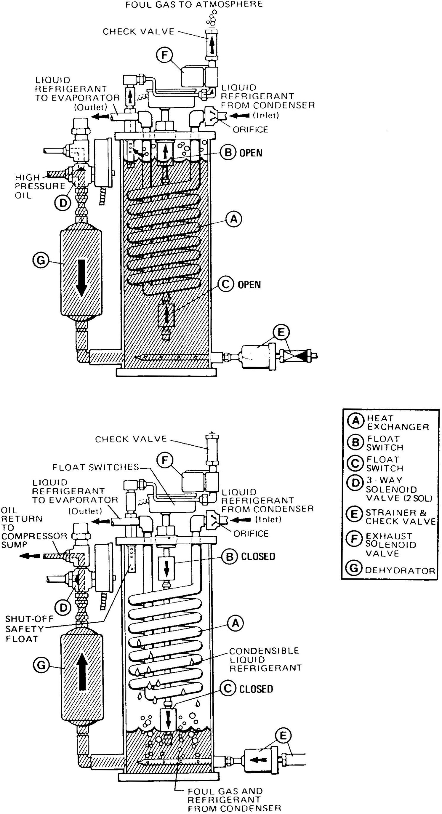
York Unit: Purge Recovery System
Carrier Unit: Purge Recovery System
Direct comments to William Haynes whaynes@maritime.edu
Mon, Jul 1, 1996
TSPS Engineering Manual ©1995 Massachusetts Maritime Academy