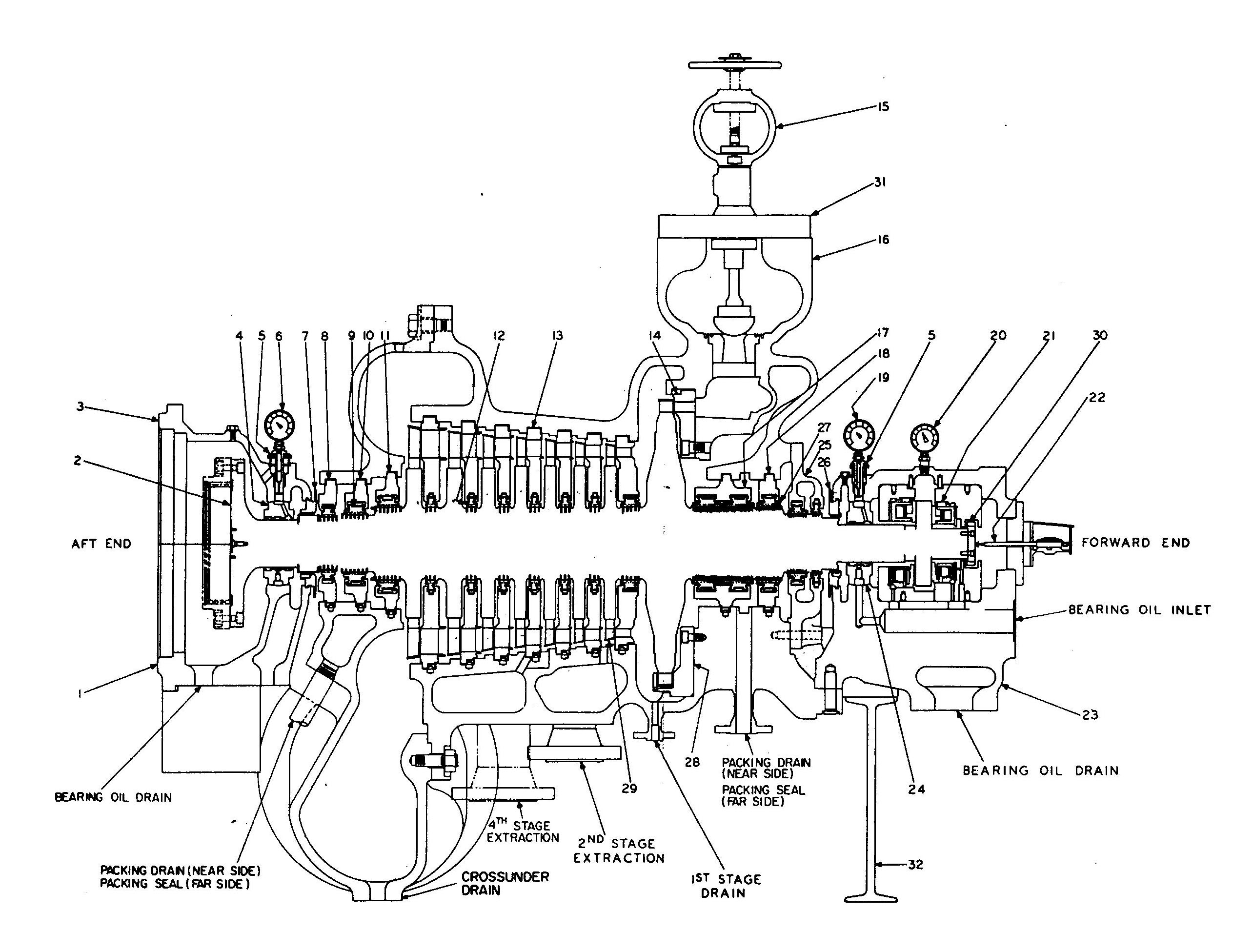
H.P. Turbine Assembly
Patriot State was the training ship of the Massachusetts Maritime Academy from 1986 to 1998.
The propulsion machinery aboard the Patriot State consists of a high-pressure and a low-pressure turbine coupled to a double reduction gear which drives a single screw. The turbines are arranged side by side and are connected by a steam crossunder pipe in an arrangement known as "cross-compound." Such an arrangement permits each turbine to operate at the speed best suited to the existing steam conditions. Because turbines operate most efficiently at high speeds, and propellers at low speeds, a reduction gear is used to couple the two to produce efficient propeller rpm.
In a cross-compound turbine, the total available energy in the steam is divided about equally between the two turbines when operating at full load, so that each performs nearly the same amount of work. The division of each turbine into stages further subdivides the total pressure and velocity of the steam into consecutively lower increments from stage to stage. Larger nozzle areas and larger blades are required with each stage because the specific volume of the steam increases as its pressure decreases. Extraction points are provided in four locations to supply reduced pressure steam for feed heating and the evaporators.
The main propulsion system is manufactured by General Electric and is designed to produce 18,000 shaft horsepower at 115 shaft rpm with the H.P. turbine at 6442 rpm and the L.P. turbine operating at 3256 rpm, under normal steam conditions. The high pressure turbines is equipped with eight stages for ahead operation. The L.P. turbine was originally equipped with eight ahead stages, but the last stage was removed in 1993, and it is also equipped with two stages for astern propulsion. Each astern stage carries a double row of blading. When operating astern with normal steam conditions, the astern turbine will develop 80% of the rated ahead torque at 50% of rated ahead speed.
Under emergency conditions, either turbine can be operated independently by means of emergency piping located in the engine room. When the H.P. turbine is used, normal pressure and temperature steam may be used, but the number of open nozzles in the high pressure head is limited to 19 to protect the reduction gear from tooth damage. When the L.P. turbine is used alone, the steam temperature must be limited to no more than 750° F. by means of an orifice in the inlet line.
H.P. Turbine Assembly
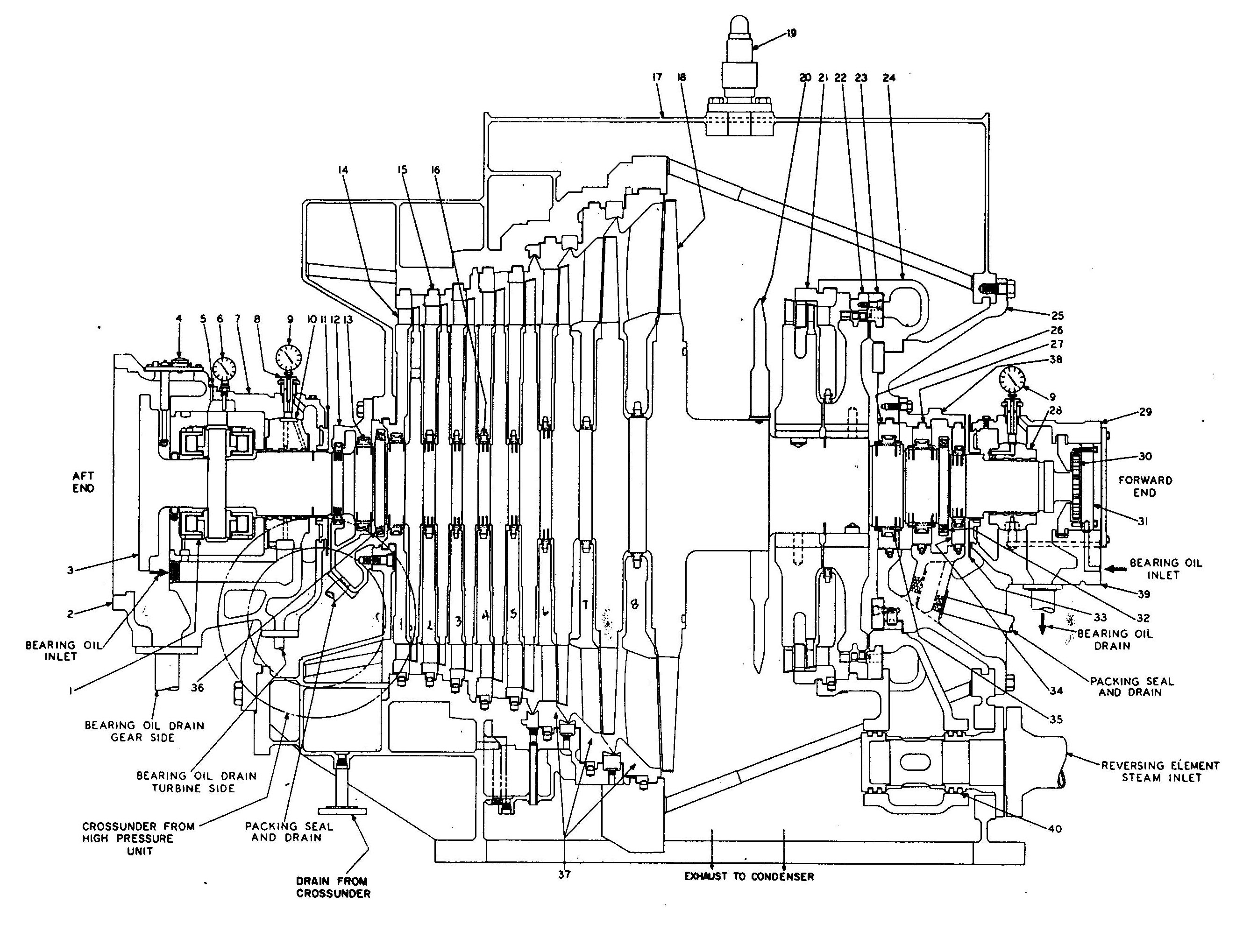
L.P. Turbine Assembly
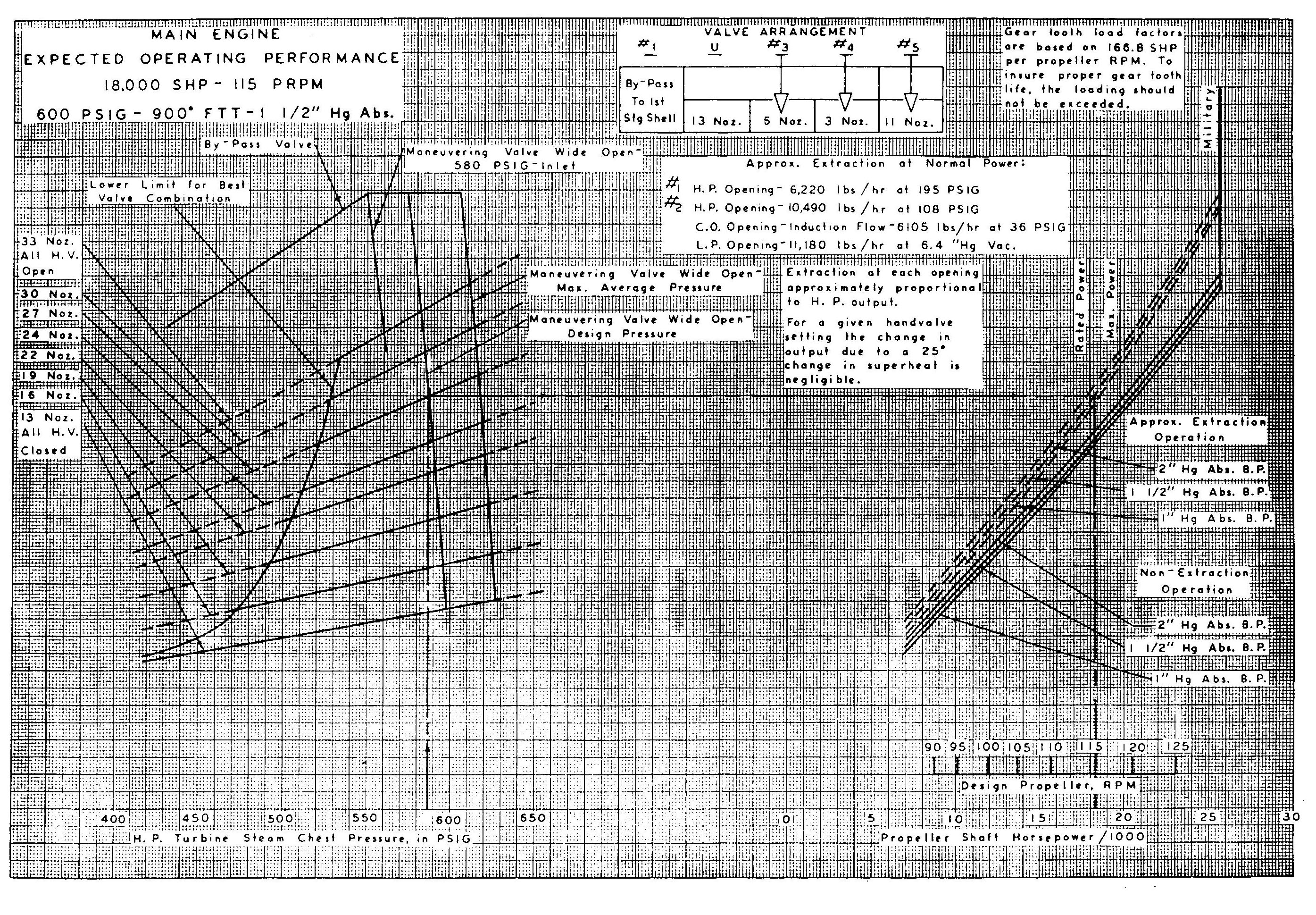
Main Engine Performance Curves
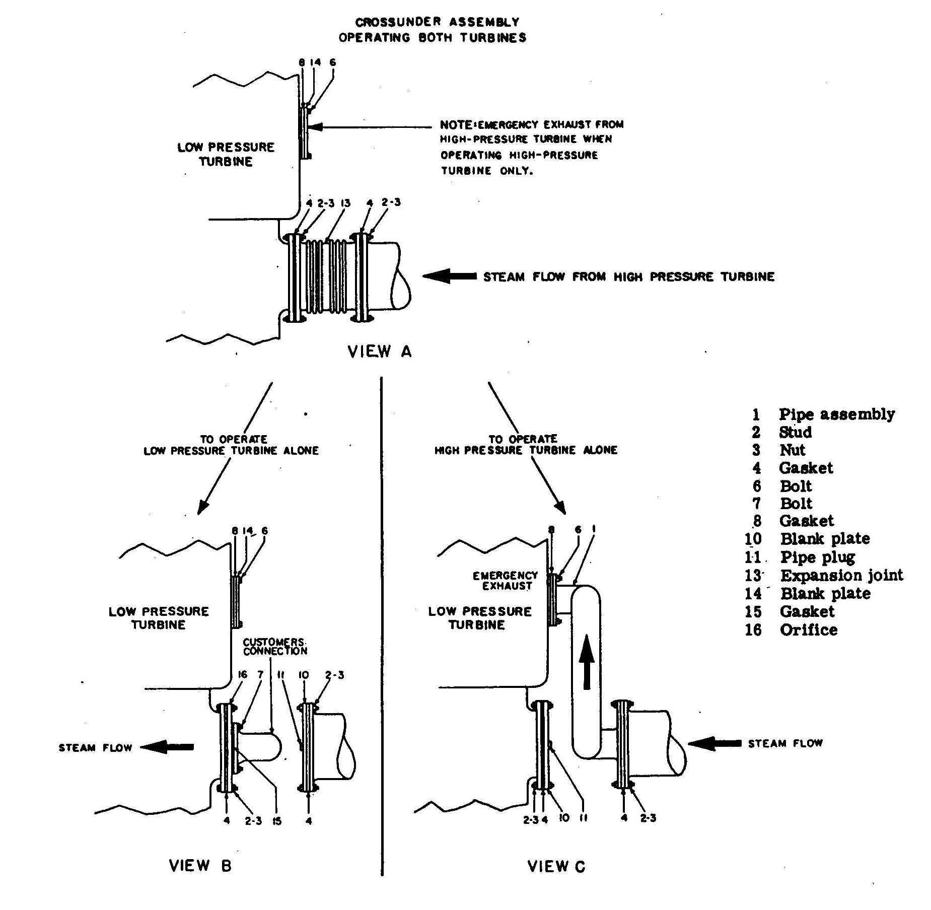
Main Engine Crossover Arrangement
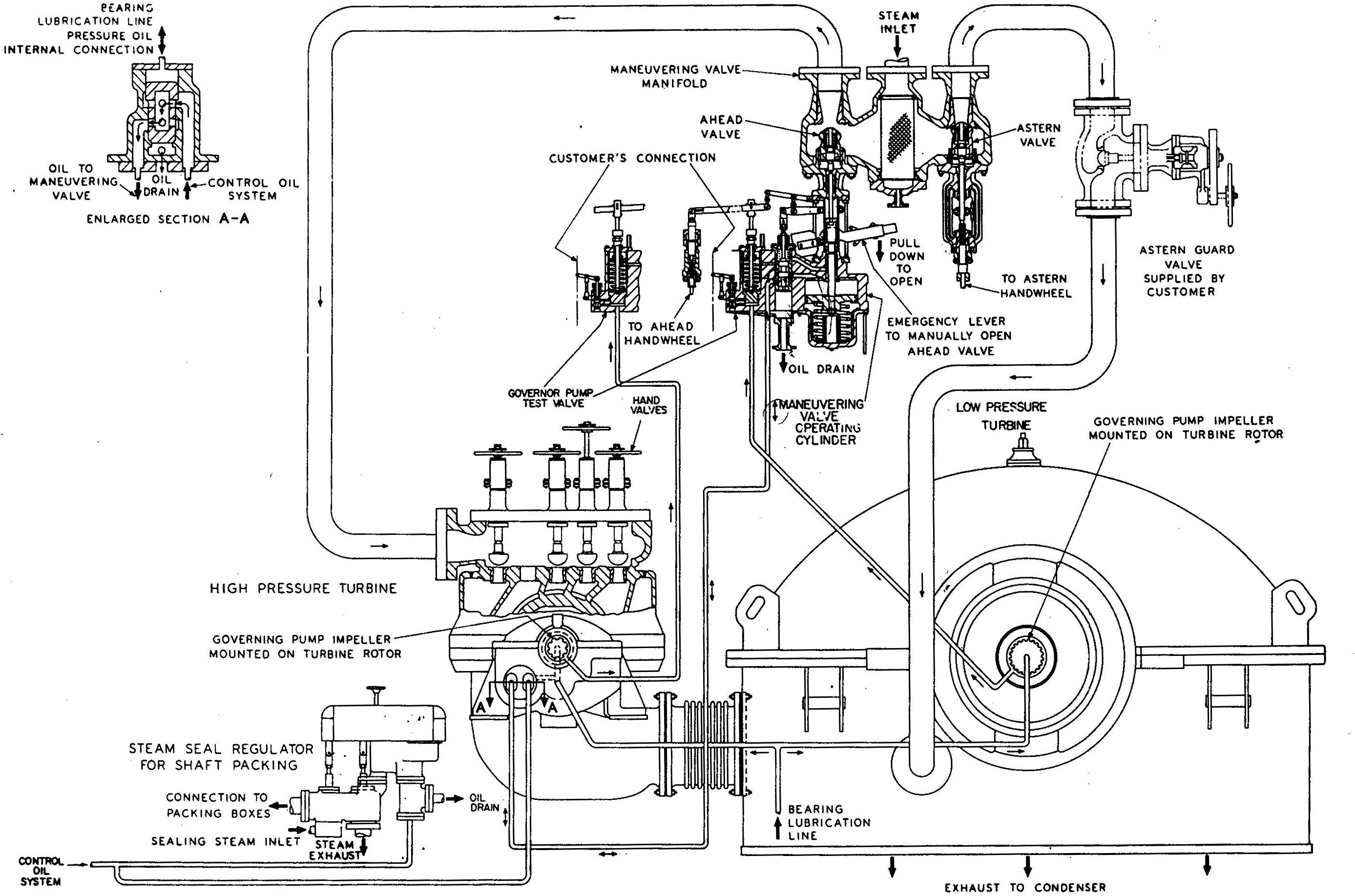
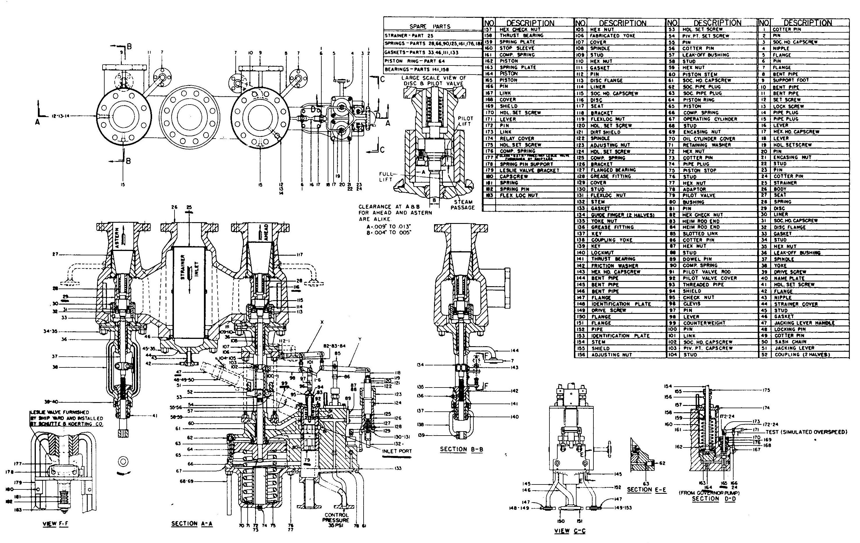
The engine is controlled by way of a maneuvering valve which consists of an ahead valve, an astern valve, a steam strainer, and two overspeed trip sensing pistons. The maneuvering valve also includes a hydraulic mechanism to operate the ahead throttle valve and a jacking lever and counterweight which permits the ahead valve to be opened manually in the event of loss of oil pressure or other emergency. Steam entering the the strainer body can be directed through either the ahead valve to the ahead elements of the H.P. turbine or through the astern valve to the astern elements of the L.P. turbine, depending on operating conditions.
The ahead valve is opened hydraulically. When the ahead handwheel is turned in the open direction, a pilot valve opens permitting control oil to act on a large operating piston. The piston moves downward against a spring and opens the ahead valve to admit steam to the ahead turbine. As the ahead valve opens, the pilot valve simultaneously closes shutting off the flow of oil to operating piston and stopping the motion of the ahead valve. This arrangement permits fine adjustments of the ahead valve with very little force by the throttle operator.
The astern valve is opened and closed mechanically simply by turning the astern handwheel. Steam must pass through an astern guarding valve in order to reach the astern elements.
Turbine Control System
Maneuvering Valve
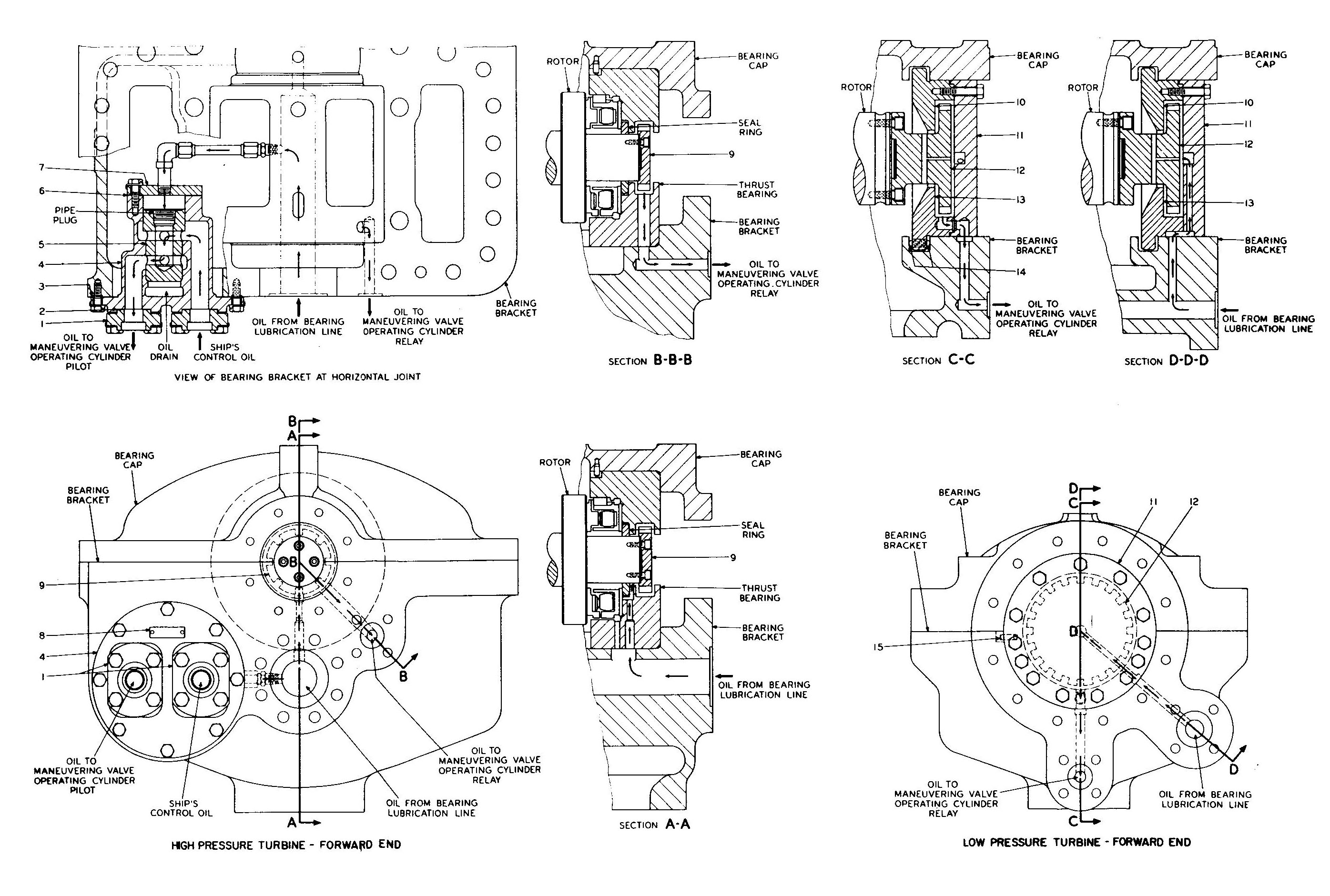
An overspeed governor oil pump is mounted at the forward end of each turbine rotor. These pumps supply oil under pressure to the overspeed sensing pistons in the maneuvering valve. The pump impellers are supplied with oil from the bearing lubrication lines. The oil pressure developed by each pump increases with increasing turbine speed. When the pressure increases to a value corresponding to 108% of the maximum rated speed, the sensing piston on the maneuvering valve causes a pilot valve to open and drain oil from the operating piston to close the ahead throttle valve. When the turbine speed returns to normal, the ahead valve opens again. The sensing pistons can be operated manually and independently to simulate an overspeed condition on either turbine.
A low oil pressure relay is located in the lower half of the forward bearing bracket of the high pressure turbine. This relay senses bearing-oil pressure and acts to close the ahead throttle whenever the lube oil pressure drops below a safe value. During normal operation, 12 psi bearing-oil holds a relay piston against its seat and directs 35 psi control-oil to the pilot valve in the maneuvering valve. If bearing-oil pressure is lost, control-oil pressure unseats the relay and drains the maneuvering valve control-oil line, causing the ahead throttle valve to be closed by the action of the spring. When bearing-oil pressure is restored, the relay piston is again seated to allow control-oil to flow through the open ports to the maneuvering valve. The ahead valve is thus opened automatically to admit steam to the turbines.
Governor Pump and Low Oil Pressure Relay
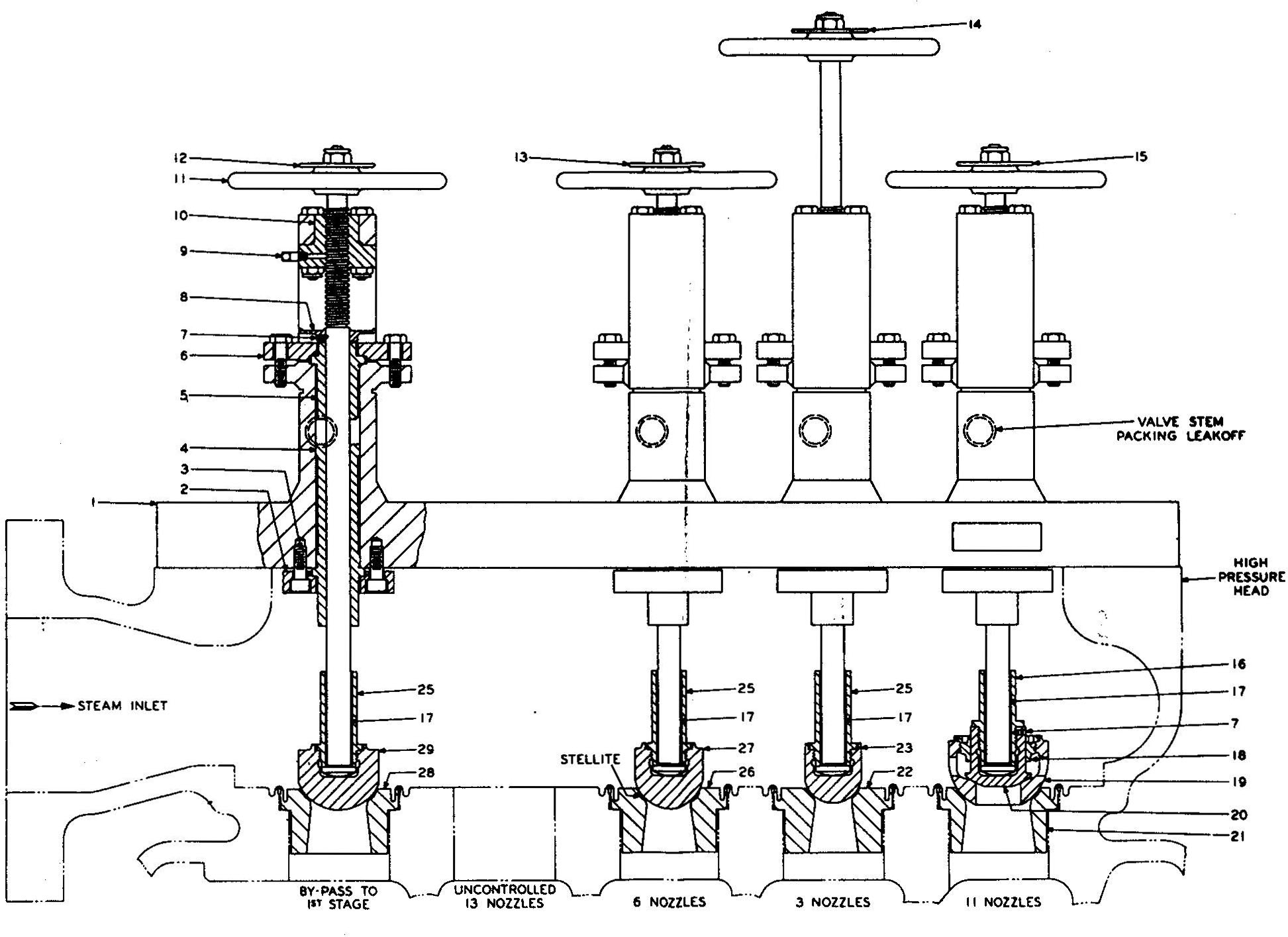
In addition to the 13 uncontrolled nozzles three manually operated nozzle control valves are provided to control the steam flow through additional groups of nozzles in the first stage of the H.P. ahead turbine. A fourth handwheel controls the steam by-pass around the nozzles and directly to the first stage of the turbine. This design makes it possible to adjust the total nozzle area for maximum efficiency at different operating conditions. Proper adjustment of these valves permits the turbine to be operated with the main throttle valve fully open over a wide range of power, and thus throttle losses can be minimized. Proper use of the adjustable nozzles is shown on the performance curve on page 3-4.
Hand Valve Assembly
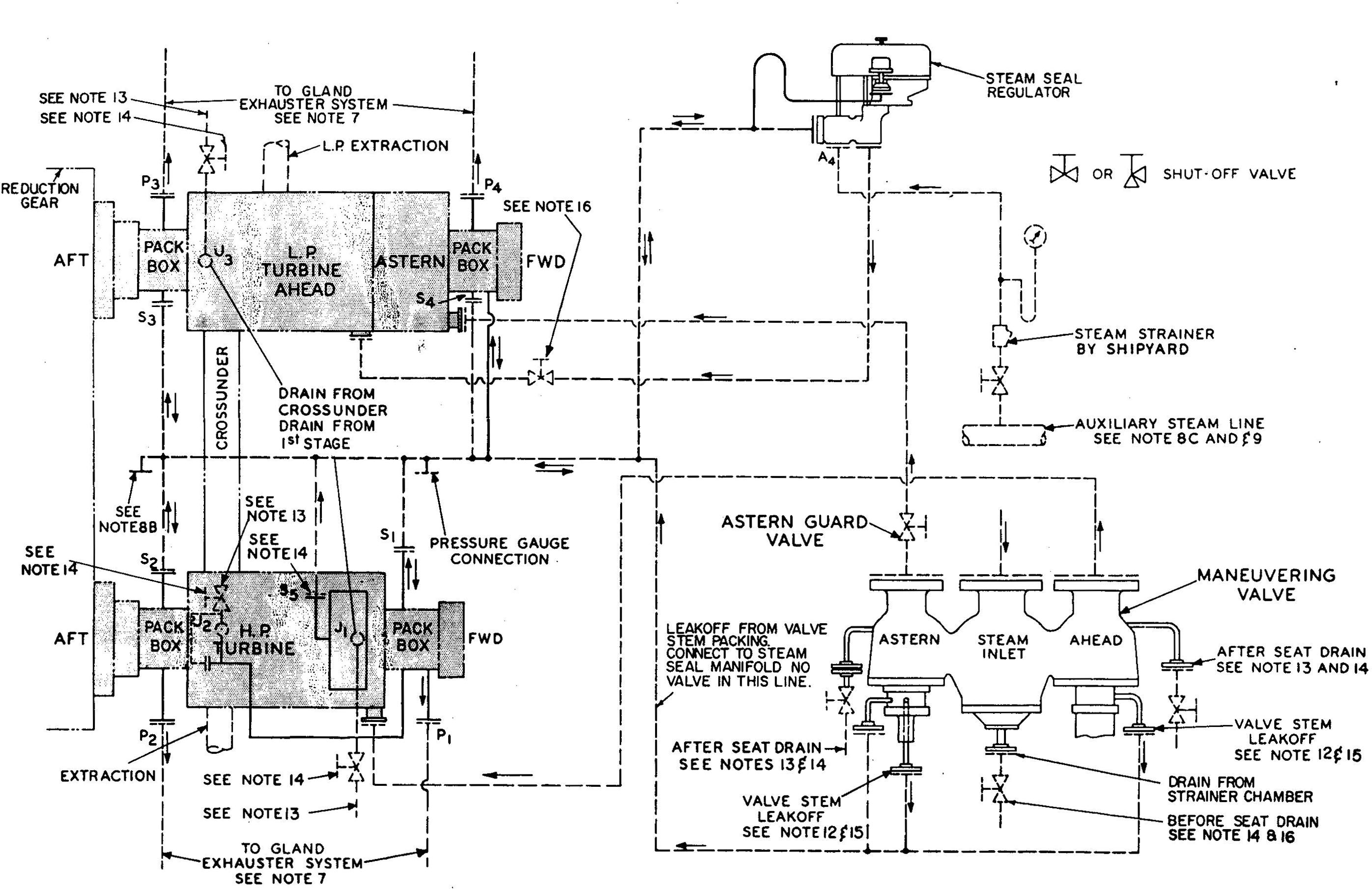
The turbine gland sealing system supplies steam to the shaft glands of the main propulsion and generator turbines, to prevent the leakage of air past these glands with the attendant loss of condenser vacuum. The system also recovers excess sealing steam when the turbines are operating as high loads and are self sealing.
When starting up at low speeds and when going astern, sealing steam for the main propulsion turbines is supplied from the 150 psig auxiliary steam system. A gland seal regulator automatically regulates the pressure in the steam header, maintaining 1-1/2 to 3 psig by admitting steam from the auxiliary steam system. As the load increases, internal pressure at the H.P. end of the turbines increases and the regulator closes in on the steam supply. At higher loads, excess steam is unloaded by the gland seal regulator to the L.P. turbine fifth stage or to the main condenser. The hydraulically operated sealing and unloading valves are actuated by oil from the ship's L.O. system steam leak-off steam from the maneuvering valve is led to the gland sealing circuit.
Gland sealing steam make-up lines from the 150 psi steam system as well as the low point in gland seal lines are drained to fresh water drain collecting systems via thermostatic traps. The line for excess unloaded by the gland seal regulator is drained by a 1/2 inch drain line fitted with an orifice to the main condenser hotwell.
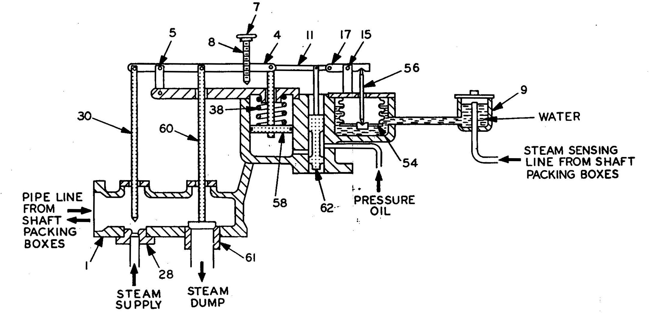
Gland Seal Regulator: Schematic view
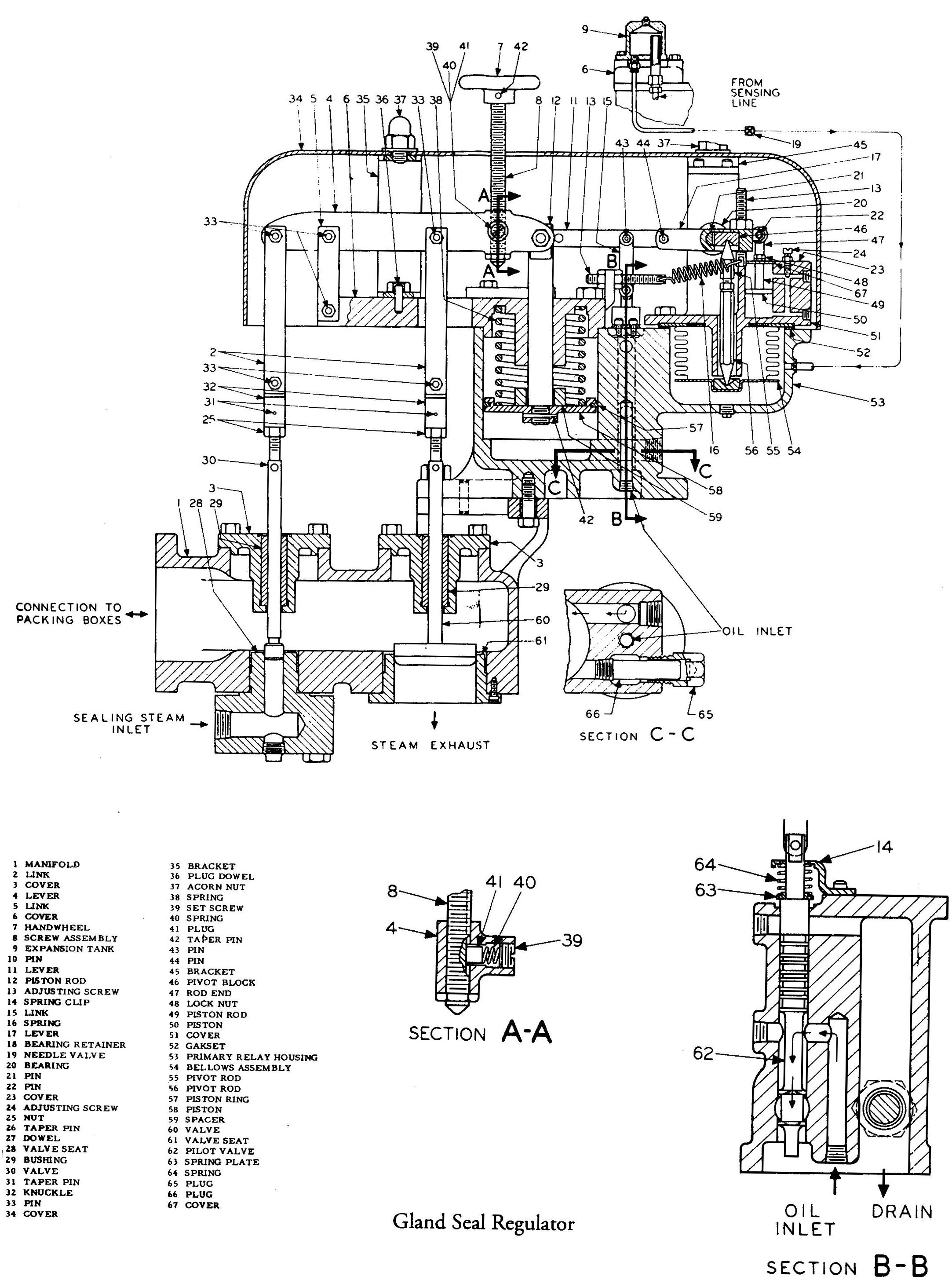
Gland Seal Regulator: Cross Section
Turbine Gland Seal and Drain Systems
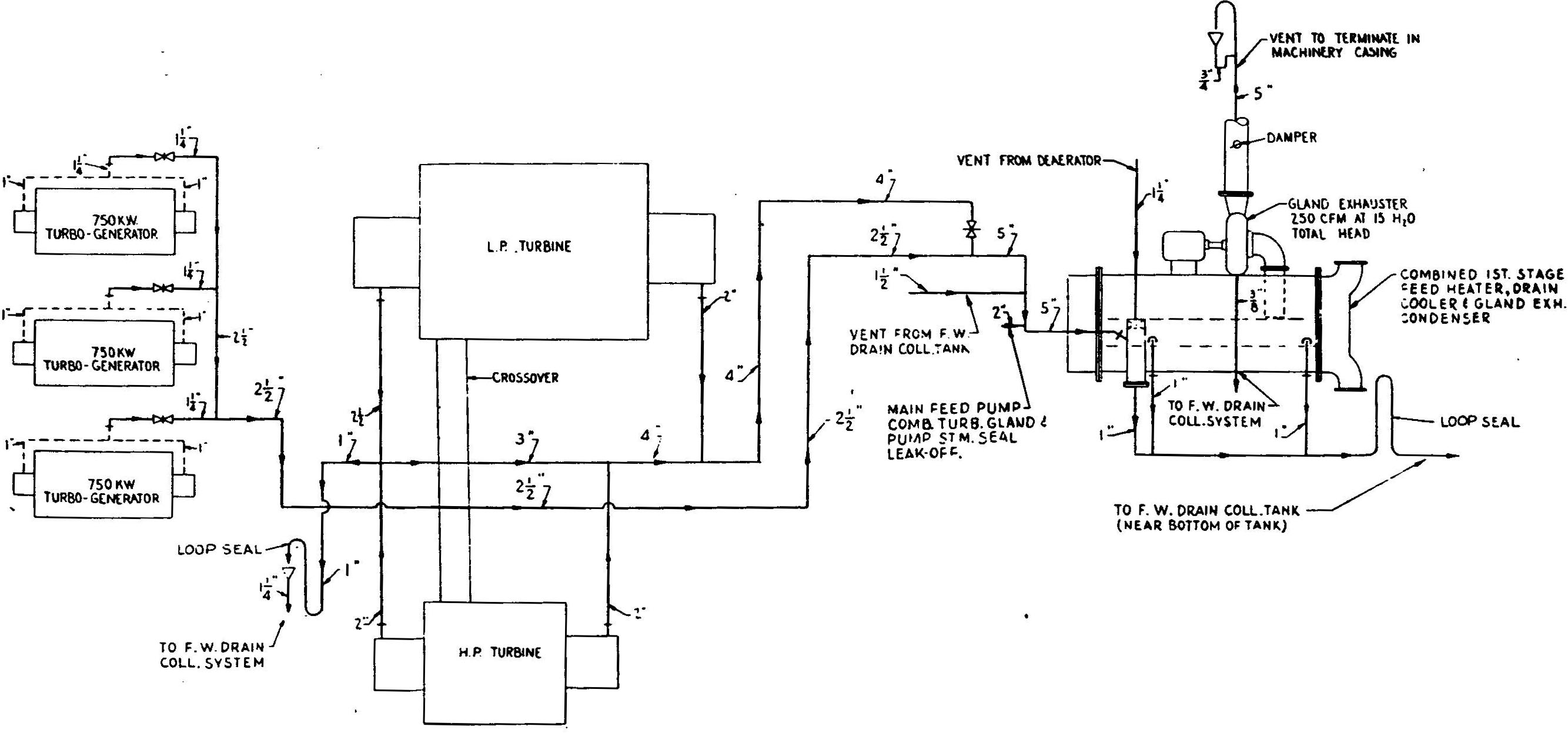
Turbine Gland Exhaust System
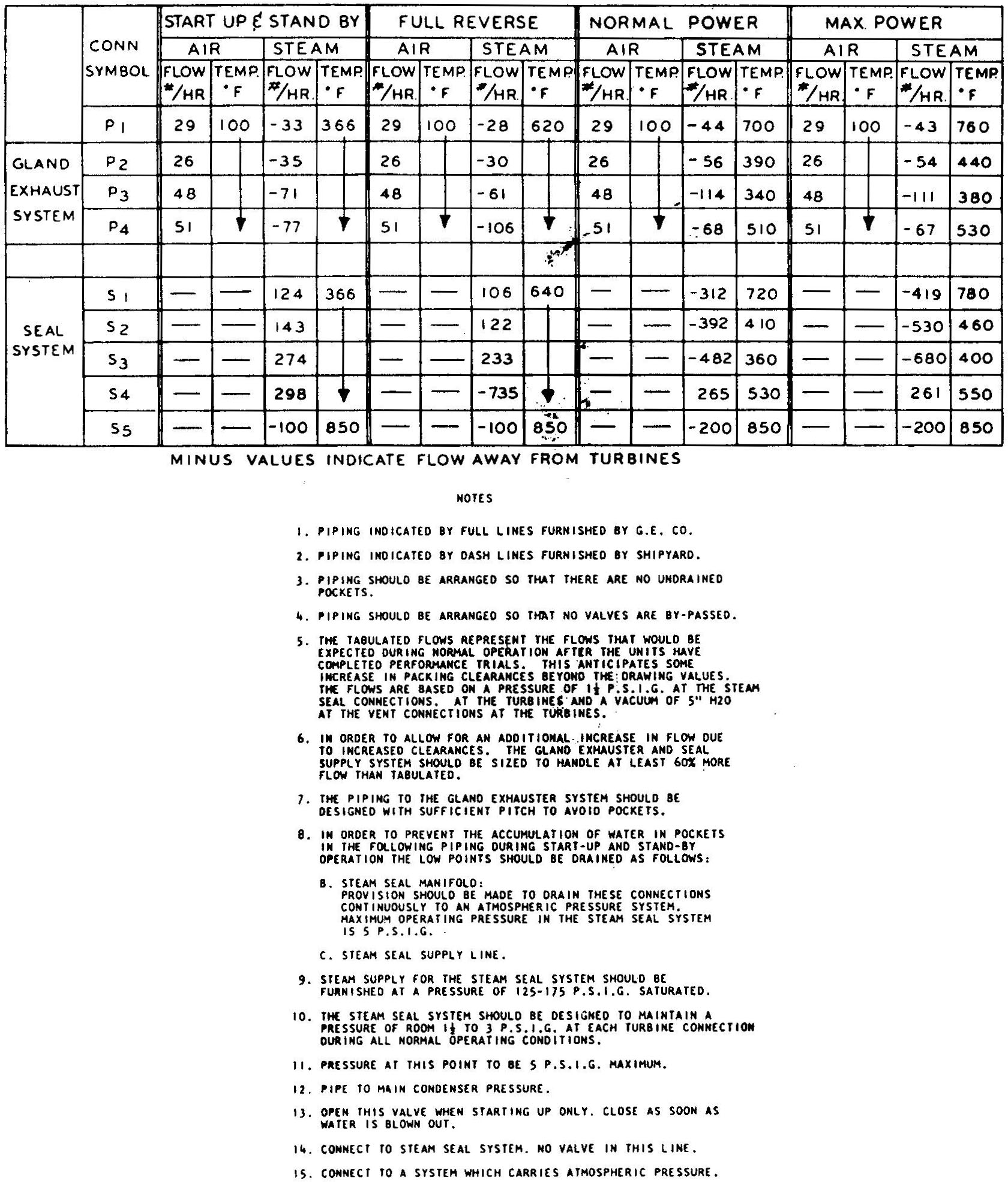
Gland Seal Steam Flows
Direct comments to William Haynes whaynes@maritime.edu
Mon, Jul 1, 1996
TSPS Engineering Manual ©1995 Massachusetts Maritime Academy