Feedwater Regulator System
Patriot State was the training ship of the Massachusetts Maritime Academy from 1986 to 1998.
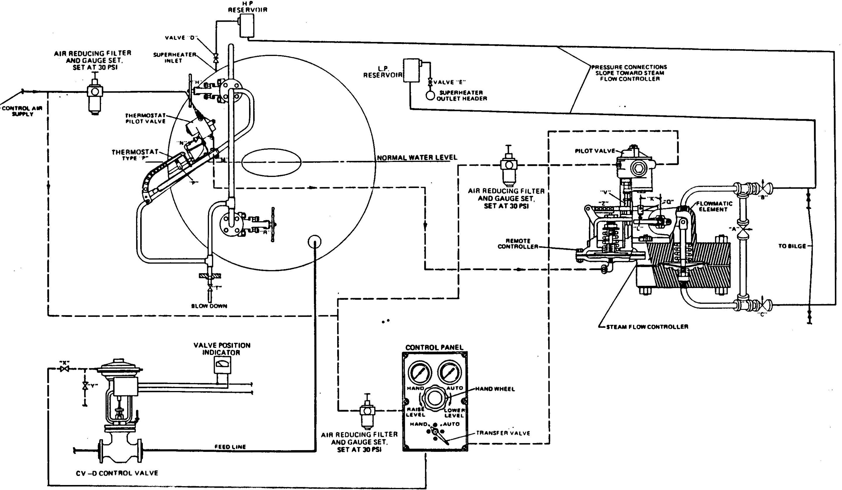
The ship is fitted with a Copes Feedwater Regulator System. The principal parts of the system are the type "P" thermostat with steam flow controller, the feedwater control valve, and the transfer and loading panel (control panel).
Feedwater Regulator System
The thermostat consists of an inclined stainless steel expansion tube mounted in a rigid channel steel frame. The upper end of the tube is connected to the steam space of the boiler drum end, the lower end to the water space. Water level in the tube always corresponds to that in the gauge glass.
Water in the lower half of the expansion tube is cooler than steam in the upper half due to radiation. Thus, the tube cools and contracts as level rises. It heats and expands as level falls. Since upper end of the tube is fixed to the frame, any tube contraction or expansion rotates the thermostat lever. Outer end of the lever rises as water level rises.
Lever motion is transferred through a bell crank lever to the stem of a pilot valve. This pilot varies air pressure in a control line in proportion to boiler water level. Control pressure increases as water level rises. The pilot is supplied with constant pressure air. It is pressure compensated so that it uses air only during water level changes.
Controlled air pressure from the pilot is piped to a Copes type "P" steam flow controller. This device includes a diaphragm type remote controller and a flow element.
The remote controller is a spring loaded diaphragm which is connected to controlled pressure from the thermostat. The diaphragm position follows this pressure and thus is proportional to boiler water level.
The flowmatic element provides a motion which is related to boiler steam flow and thus is proportional to boiler feed requirements. The flowmatic element consists of a spring loaded diaphragm in a pressure chamber. One side of the diaphragm is connected to boiler drum pressure and the other side to superheater outlet pressure.
Pressure loss through the superheater increases with boiler load. This pressure difference acts across the flowmatic diagram and is balanced by the spring. Thus, the diagram moves in response to changes in boiler load.
Movement of the flowmatic element and remote controller are combined mechanically by external linkage. The combined movement positions the stem of a pressure compensated pilot valve. This pilot is supplied with constant pressure air. As the pilot stem is moved, the pilot changes air pressure in a control line. The control line is connected to a diaphragm receiver of the feedwater control valve.
The control valve is a diaphragm type feedwater control valve. The diaphragm moves in response to air impulses received from the steam flow controller via the control panel.
This valve is designed to shut as control pressure increases (lower boiler load or higher water level). For each change in control pressure, there is a proportional change in opening the feedwater control valve. Amount of feed is therefore controlled by both boiler steam flow and water level.
Effect of steam flow and water level can be predetermined by adjustments at the thermostat and steam flow controller. By proper adjustment of steam flow influence, the valve will be automatically positioned as required to feed the boiler at all loads. This results in constant water level at all loads. The thermostat serves merely as a check on the flowmatic element and to take care of minor discrepancies in water level.
The regulator can also be adjusted to hold automatically a lower water level at minimum boiler load than at maximum load. This type of regulation permits fuller utilization of drum space to absorb the swell in water level that occurs at a sudden increase in boiler load, and thus reduces the possibility of carryover.
Normal water setting (level that is automatically held by the regulator) can be changed by adjustments at the thermostat.
The regulator permanently retains water level setting and type of control characteristics selected. Thus, no periodic readjustment is necessary.
The flowmatic regulator responds instantly to sudden changes in boiler load and water level that occur during maneuvers. When load is suddenly increased, more steam bubbles are formed in the boiler tubes. Steam bubbles displace some water, forcing it into the boiler drum and causing a sudden rise in level known as "swell." Regardless of how feed is controlled, this swell requires appreciable time to boil away. The flowmatic regulator will restore the level to normal quickly. At the same time, the flowmatic eases the effect on the feed pumps of boiler load change.
Conversely, when steam load is suddenly reduced, a "shrink" in water level results, and time is required to restore level to normal.
The control panel provides for remote manual positioning of the control valves. Normally, Transfer Valve Pointer handle is at the Auto position. Controlled pressure from the thermostat pilot merely passes through the transfer valve and on to the control valves. However, when Transfer Valve Pointer handle is thrown over to the Hand position, controlled pressure from the thermostat is cut off and the control valve is connected to the Hand Loading valve on the panel.
The hand loading valve is a reducing valve which is supplied with constant pressure air through a second reducing valve. As hand loading valve is opened, supply of air to control line is increased. This builds pressure in control lines. Controlled pressure can therefore be varied by changing the opening of the hand loading valve. This feature is useful when feeding manually, for example, during periods of raising steam.
Pressure gauges on the panel indicate automatic control pressure and manual control pressure at all times. This makes it possible to switch from automatic to hand control at any time with no disturbance to feed flow. It is merely necessary to bring hand loading pressure equal to automatic controlled pressure before the transfer valve is switched.
Ample adjustments are provided at the thermostat to adjust water level held by the regulator, and to widen or narrow water level variation over the boiler load range. Rough adjustment of the position of the thermostat lever is accomplished by the adjusting sleeve at upper end of the expansion tube. Final adjustment of water level is obtained by using the adjustable ball-point on the Slide Adjustment.
One single inlet, backward curved, multiblade, centrifugal type forced draft blower is provided for each boiler. Each blower normally delivers about 24,500 CFM of free air at 100° F. against approximately 13.6 inches of water static pressure. Each blower is capable of a maximum design capacity of 36,150 CFM of free air of 100° F. against 28.3 inches of water static pressure. Each blower is directly connected through a flexible coupling to a four speed electric motor of 200 H.P. at 1700 rpm.
Either of the two forced draft fans onboard are designed to carry both boilers steaming at low loads. Should either the port or starboard forced draft fan fails, you can continue to fire both boilers at a reduced steaming rate using the cross-over ductwork. Looking at the diagram should the port fan fail, you would close valve #2 and open valve #3 to divert the forced air from the starboard fan to both boilers. The starboard fan would be able to maintain both boilers at a low steaming rate while on high speed. Should the starboard fan fail, you would close valve #1 and open valve #3 to have the port forced draft fan maintain both boilers. If you were to operate only the port boiler using the starboard fan, you would close the registers on the starboard boiler, close valve #2 and open valve #3. At low steaming rates, you must also by-pass the air preheaters. This is done by opening the four dampers on each airheater.
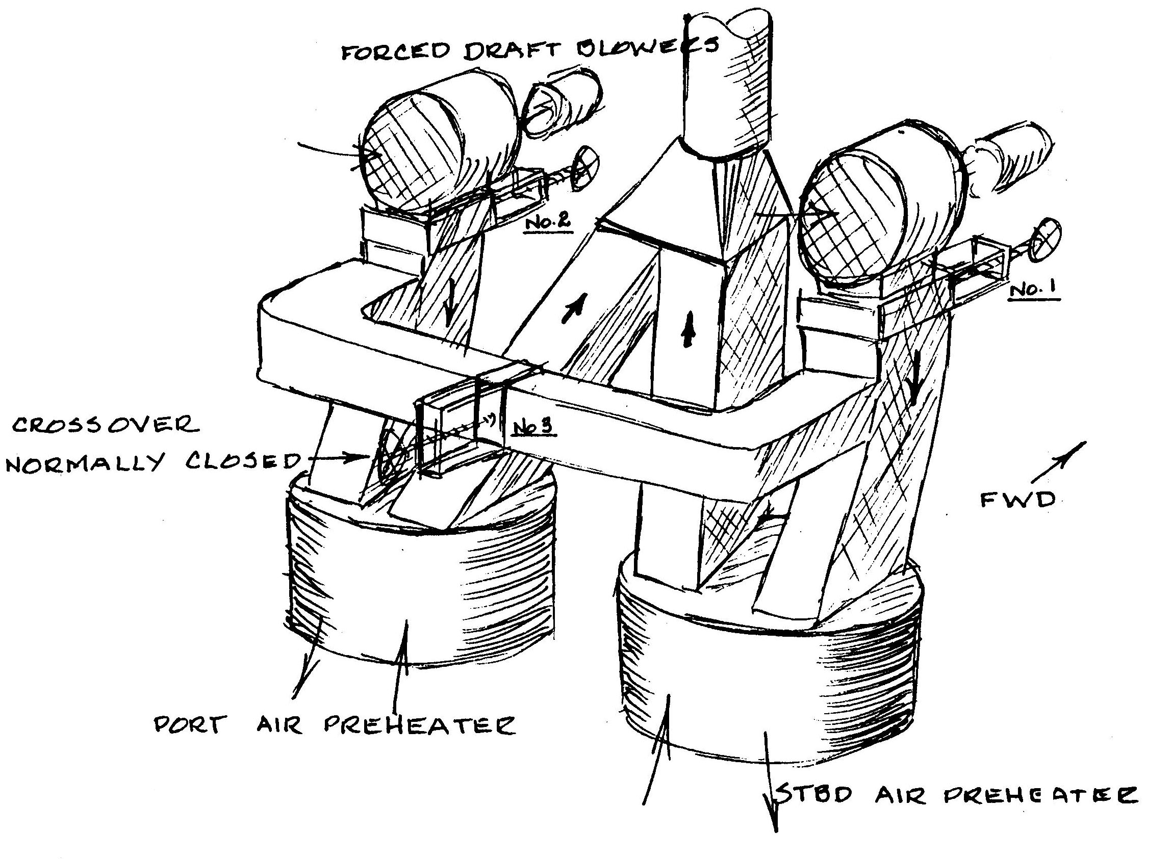
Forced Draft Blowers and Ductwork
Each boiler has one Ljungstrom vertical continuous counter flow regenerative type air preheater size 14, VMX-48 manufactured by the Air Preheater Corporation. The regenerative type preheater consists of a series of parallel plates on a horizontally mounted wheel. The unit is divided into two sections of which the motor driven wheel (rotor) passes through both continuously at about 2 rev/min.
The cool incoming air from the forced draft fans pass through one side of the heater on the way to the double casing front to the oil burners. The hot exhaust gases pass up through the separate side of the heater on its way up the stack. The rotating plates are heated as they pass through the hot gases and liberate the heat as they rotate through the cool intake air. Radial seals located on the cold end of the air heater prevents the passage of hot exhaust gases to the air side and back down the double casing. Air heaters raise the efficiency of the plant 1% for every 40° F. rise in the incoming air temperature.
The cold end of the heater is exposed to severe heat conditions and sulfuric acid deposits. These plates are coated with porcelain to protect them from the corrosive conditions. The elements in the cold end are placed in buckets of Corten, installed and supported independently of the hot end layer.
In order to remove the elements packed into the baskets for cleaning, special arrangements have been made for removal through the outer shell.
The drive unit consists of a low speed hydraulic unit with the motor connected directly to the rotor shaft. The Ljungstrom air preheater take up only 1/3 the volume (area) of a tubular type of the same capacity.
Two soot blowers are provided for the removal of accumulated deposits along the heating surface. These electrically driven automatically controlled sootblowers are installed in the outlet area of the gas side and inlet area of the air side.
Air leakage due to leaking radial seals is the principle source of trouble. These leaks would make the measured exit gas temperature appear lower than it actually is because of the cool incoming air being leaked up the stack. This apparently cooler exit temperature would give you a misleading preheater performance.
The air heater is provided with a by-pass so that when the boiler is operating at low firing rates, the uptake temperature can be maintained higher than the dew point of the uptake gases. This will prevent corrosive elements from the condensing vapors from settling on the heating surfaces of the air heater. As a general rule, the air preheater should be by-passed whenever the uptake temperature is less than 220° F. Also, in the event of a casualty to the air heater motor, the high exit gas temperatures would destroy the elements within the heater baskets.
The air preheater has several points that should be checked regularly while in operation. These are, the rotor drive, the guide bearing and the support bearing.
The rotor drive oil level should be checked every hour and the level kept at the line on the dipstick. Use care when checking this oil level as the dipstick can only be inserted to its lowest position when the red lines on the cap and pipe are lined up.
The guide bearing oil level should be checked at least once each watch and the oil level kept at the line on the dipstick.
The support bearing oil level should be checked every hour and the level kept between the lines on the dipstick. The temperature of the oil should be checked every hour and recorded. Should the temperature of the oil in the support bearing reach 160° F., the watch engineer should be notified at once. The pressure from the oil circulating pump should also be recorded.
The oil used on the rotor drive, the guide bearing and the support bearing is CYLESTIC TK-680. The oil and oil can are stored in a metal box forward of the preheaters on the main deck level.
The sight hole is provided to allow the watchstander a means of visual inspection of the cold end of the preheater. The watchstander should check for rotor rotation as well as the presence of any foreign matter or unusual noises.
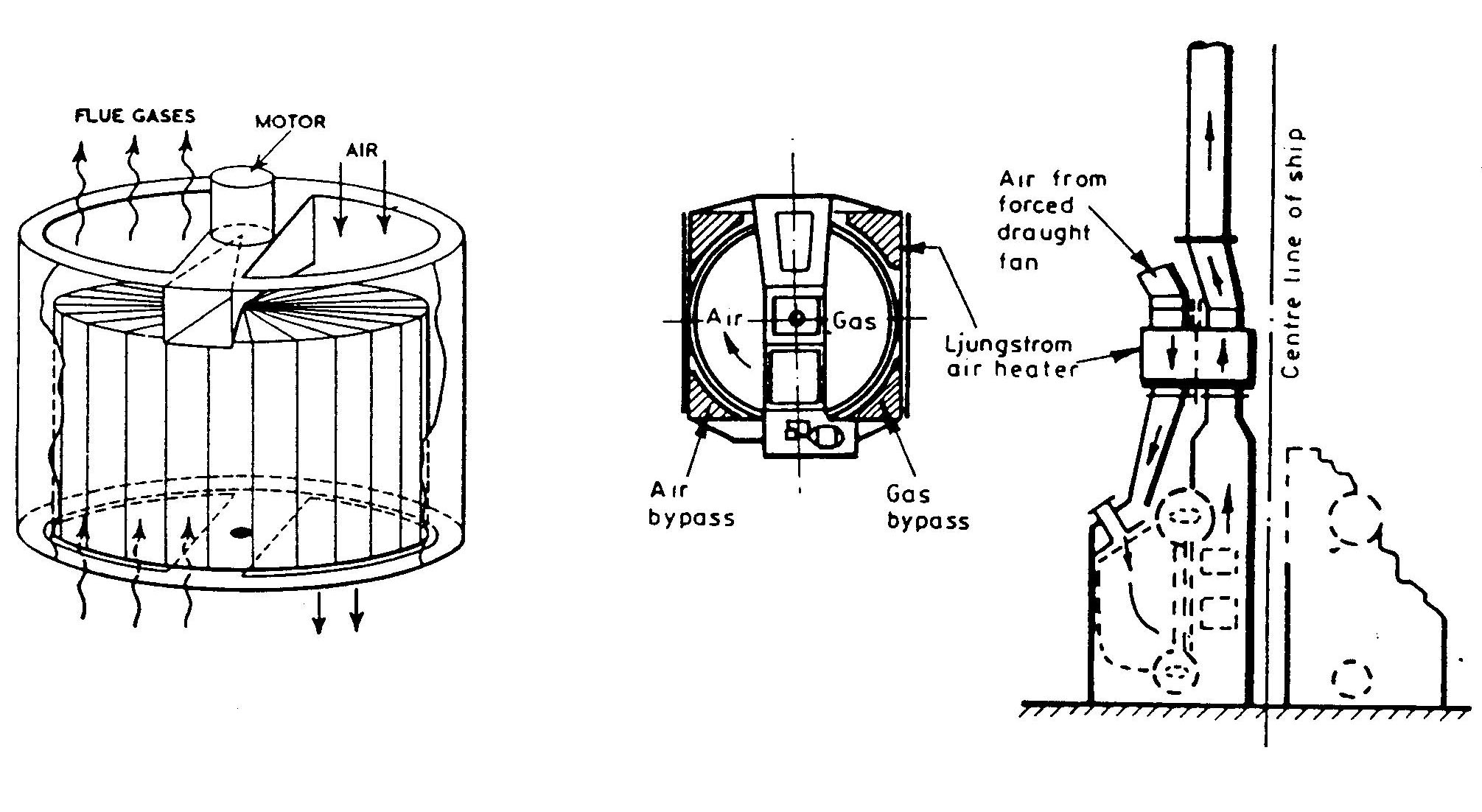
Ljungstrom Air Heater
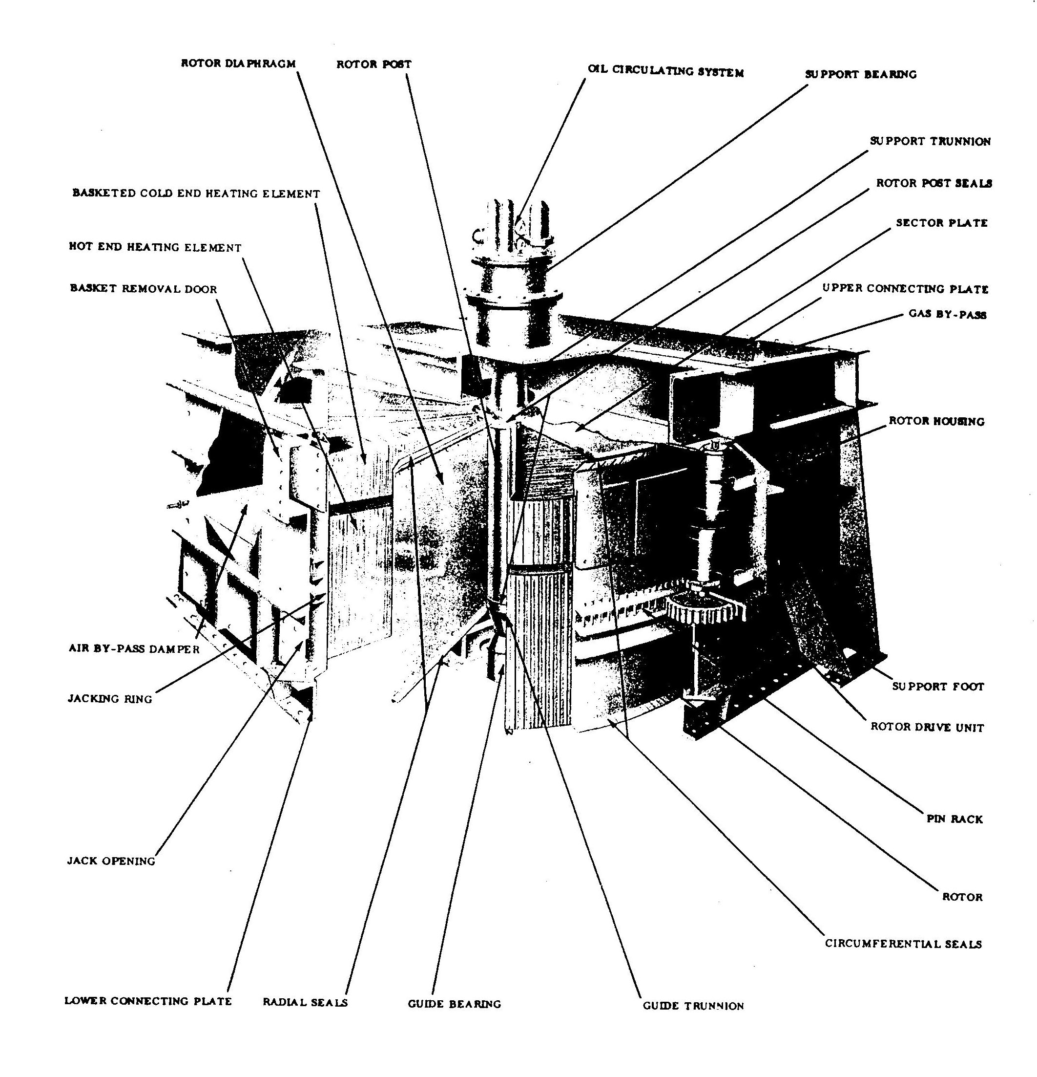
Ljungstrom Air Heater
Direct comments to William Haynes whaynes@maritime.edu
Mon, Jul 1, 1996
TSPS Engineering Manual ©1995 Massachusetts Maritime Academy