Bilge System
Patriot State was the training ship of the Massachusetts Maritime Academy from 1986 to 1998.
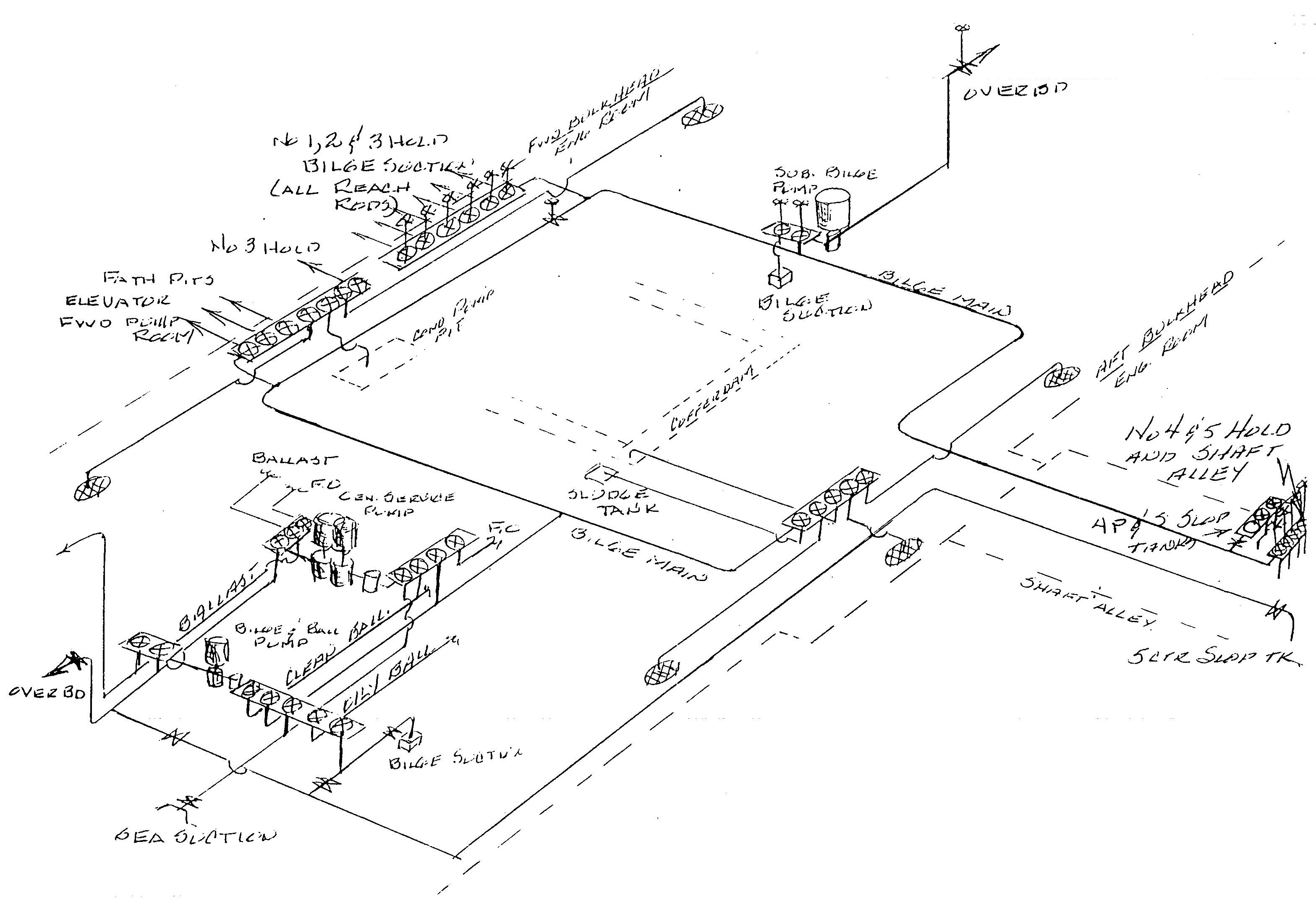
Bilge system is provided to maintain dry bilges throughout the ship and prevent the possibility of an accumulation of water or oil in the cargo holds or machinery space. It will be noted that the system is provided with one or two suctions from each compartment in the ship where drainage water may collect.
Bilge suction lines are entirely separate from those used for filling or emptying tanks in which water or oil is carried.
Bilge suction lines are provided for fathometer tanks, cargo hold drain wells, cargo pump room drain, shaft alley sump, refrigerated drain wells, lube oil sludge tank, lube oil sump tank cofferdam, and engine room bilge wells. Tail pipes are led from the points where suctions are required to manifolds located at the forward bulkhead in the machinery space. The bilge manifolds are of the single, stop-check valve type.
Two separate bilge systems served by eductors provide for miscellaneous drainage: one forward for the chain locker and boatswain's stores, the other aft for the steering gear room, void space, hawser room, and carpenter shop. Power water is supplied from the firemain. Eductor suction from individual drain wells is via a stop-check valve. Combined power water and bilge drainage is discharged directly overboard via a swing-check valve.
Bilge System
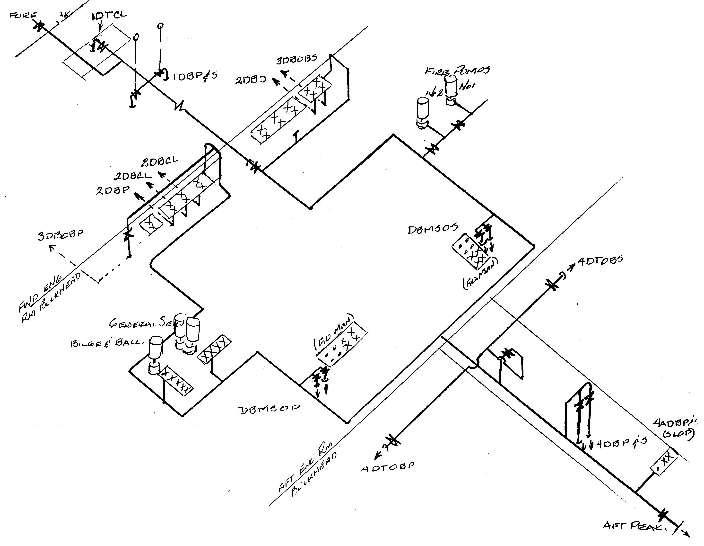
Clean ballast system is provided for ballasting and deballasting the forward ballast tanks fore peak tank, the after ballast tanks and aft peak tank required for ships trim and stability.
The clean ballast main runs from the machinery space forward to the ballast tanks and fore peak tank, and aft to the ballast tanks and aft peak tank. The firemain services the clean ballast main. Suction from the clean ballast main is taken by either the bilge and ballast pump or the general service pump via associated manifolds and discharged overboard via manifolds.
The bilge and ballast system is served by three pumps: the bilge and ballast pump, the general service pump, and the submersible bilge pump. In addition, the main circulating pump also can take suction from the bilge.
The general service pump is a vertical, duplex, double acting, 14" x 10" x 12" steam driven reciprocating unit with dual capacity, 600 gpm at 25 feet total head or 225 gpm at 100 feet total head.
The bilge and ballast pump is a vertical, single stage, centrifugal, double suction, direct motor driven unit with a capacity of 600 gpm at 60 feet total head. The bilge pump is primed by an integral centrifugal displacement type priming pump. The air handling capacity of the primer is 34.5 cfm.
The submersible bilge pump is a vertical single stage, centrifugal, motor driven unit capable of 600 gpm at 60 feet total head. The submersible pump is primed by an integral centrifugal, displacement type pump capable of handling air at 12 cfm. The pump is capable of developing rated capacity and head when submerged to a depth of 40 feet measured from centerline of impeller.
All pumps used for bilge service, with the exception of the main circulating pump, are provided with direct overboard discharge connections.
Clean Ballast System
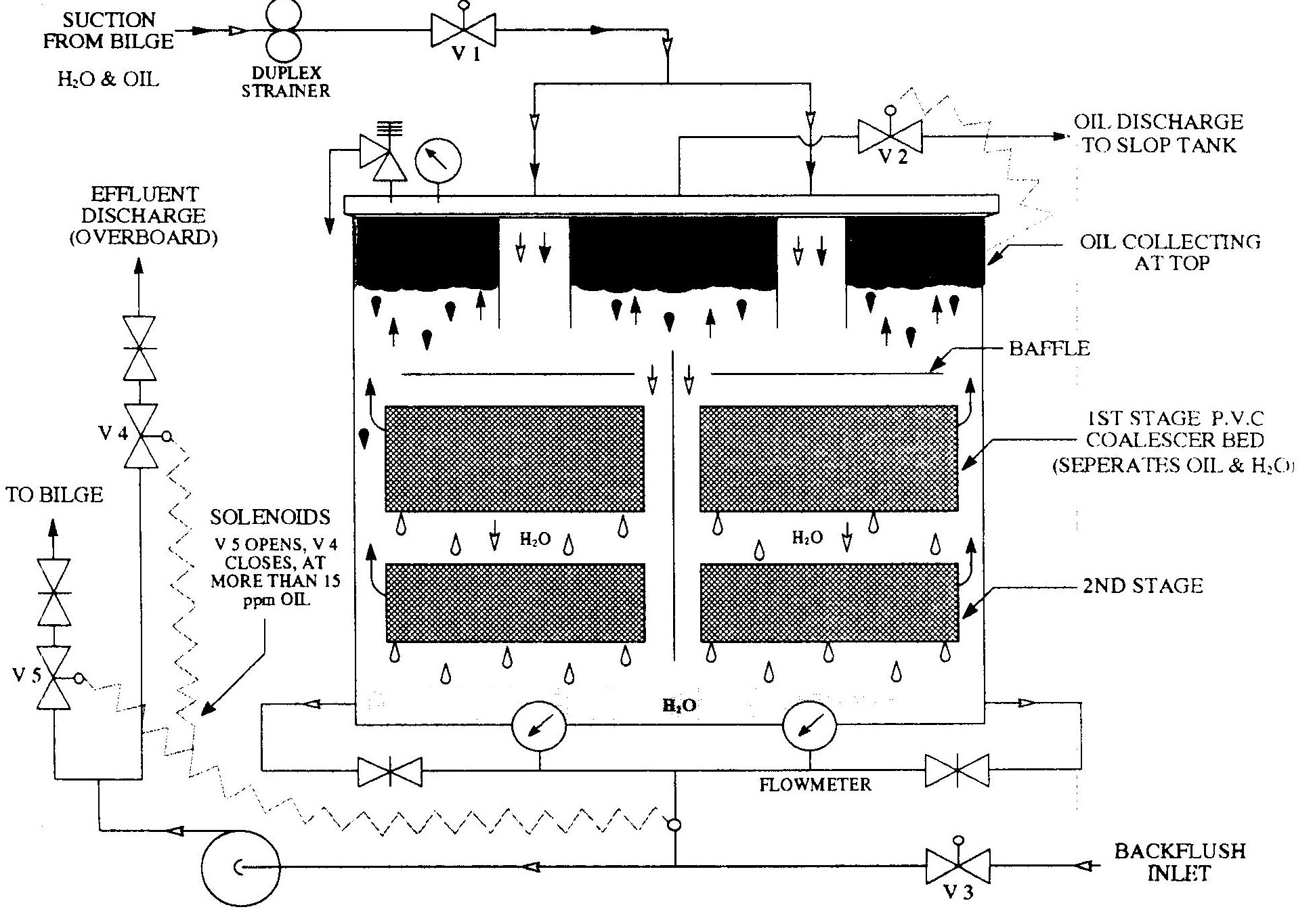
The oily water separator is provided to eliminate engine room bilge water in accordance with current pollution prevention regulations by discharging water containing no more than 15 ppm of oil overboard.
The unit, manufactured by Sigma Treatment Systems, consists of a duplex tank divided into several zones by internal baffles, and filled with oleopylic-hydrophoic (oil attracting-water repelling) polypropylene coalescer beads. A positive displacement pump, mounted downstream of the separator, pumps treated water out of the tank and simultaneously draws unprocessed oil/water into the separator.
As the oil/water mixture flows through the tank, oil droplets are attracted to the coalescer beads while water is repelled. Water passes around the beads but oil temporarily attaches to them. Oil droplets accumulate on the beads until they become large enough to break away and float to the top of the tank.
Meanwhile, the treated water is pumped from the bottom of the tank, through an oil content monitor and then either overboard or back to the bilge, depending on residual oil content. Effluent will only be discharged overboard when its oil content is less than 15 ppm.
Eventually the oil layer at the top of the tank increases sufficiently to trip a sensor which causes the separator to go into "Oil Discharge Mode." In this mode, the pump stops, the discharge valve closes, and the backflush solenoid opens. Water from the sanitary system flows into the bottom of the tank and up through the coalescer beads. The accumulated oil is forced out through the oil discharge valve to the slop tank. After the backflush is completed, the unit returns to the normal "Processing" mode.
Oily Water Separator
Direct comments to William Haynes whaynes@maritime.edu
Mon, Jul 1, 1996
TSPS Engineering Manual ©1995 Massachusetts Maritime Academy