Main Electrical Power Distribution System
Patriot State was the training ship of the Massachusetts Maritime Academy from 1986 to 1998.
The electrical requirements of the training ship are supplied by the electrical plant. The electrical plant consists of three turbo-generators, one emergency generator, the emergency battery system, and the electrical distribution system.
There are three 750 kW turbo-generators, arranged for individual and parallel operation with any two capable of carrying the maximum sea and port load of the ship and the third generator available for standby. Each turbo-generator is capable of a continuous rating of 750 kW, with a 25% overload for two hours.
A 200 kW emergency diesel generator is adequate for supplying power for emergency lighting, interior communication and power load requirements and also cold ship starting of the plant.
Paralleling of main and emergency generators is prevented by an interlocking circuit which trips the bus tie breaker on the main switchboard and emergency switchboard when the generator breaker is closed.
One emergency battery bank, rated at 120 volts, 204 ampere-hours is provided for the ships emergency lighting, 120 V DC bus, fire door release system, diesel starting control circuit and the manual alarm and fire detection system.
A recapitulation of data from Bender drawing 546 TV-001-301-06, electric load analysis, showing calculated loads for the turbo-generators, the emergency generator and the emergency batteries is shown below.
It is noted that calculated values exceed the requirements encountered during sea trials.
Main Distribution System
	Port Load      793.6 kW
	Cruise Load        1372.9 kW
	Training Load      1434.7 kW

Emergency Distribution System
	Emergency Load     199.8 kW

Turbogenerator Rating
	Continuous     750 kW
	2 Hour Overload        938 kW

Diesel Generator Rating
	Continuous         200 kW

Emergency Battery
	Voltage        120 Volts DC
	Capacity       204 Ampere Hours
The electrical distribution system's main purpose is to distribute and control the supply of electrical power to all auxiliary and electrical equipment aboard ship. The electrical distribution system consists the cables, busses, circuit breakers, fueses, etc., necessary to safely distribute power throughout the ship.
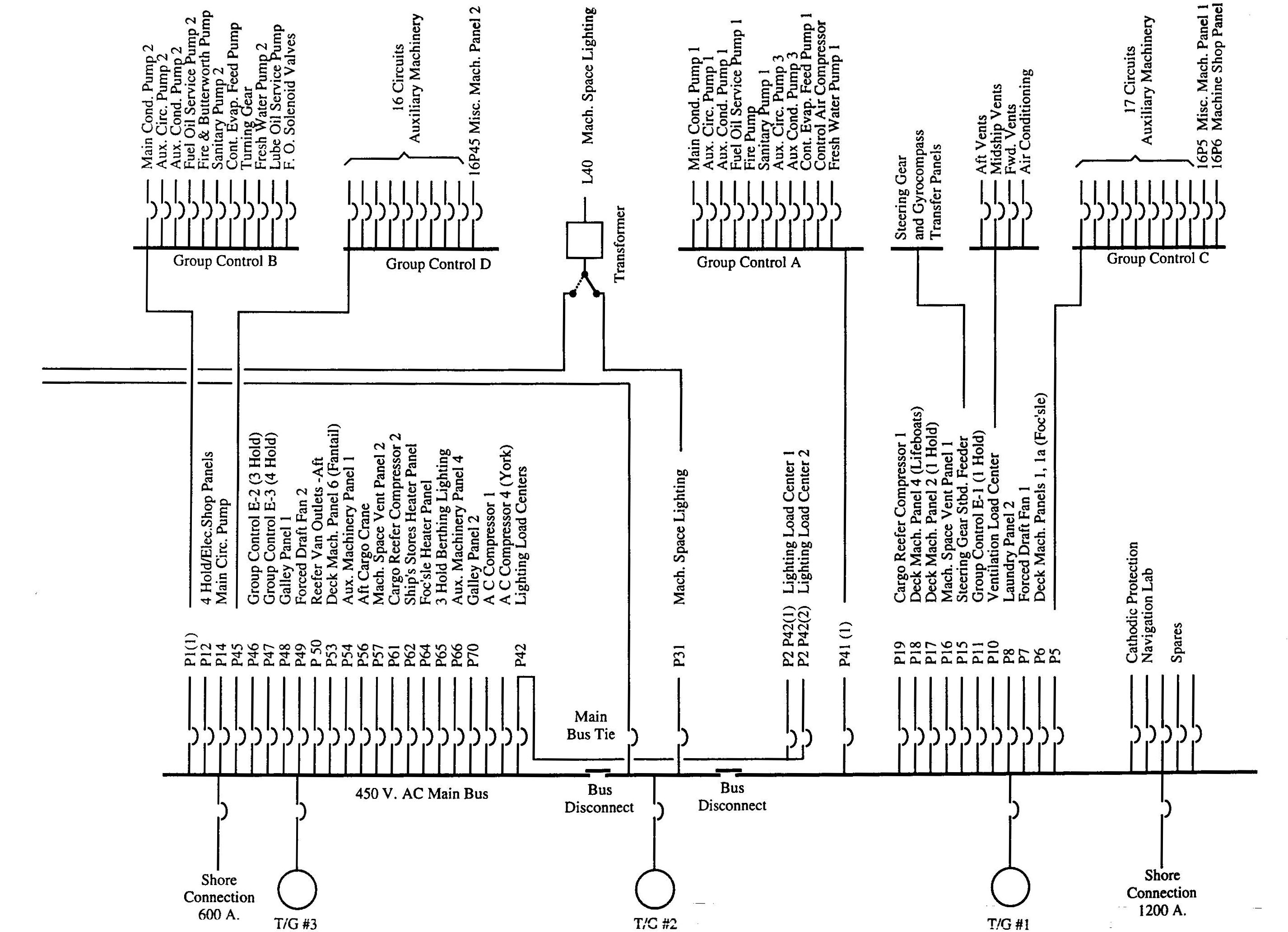
A one-line diagram of the Patriot State electrical distribution system is shown on below.
The main switchboard, as the primary distribution center, distributes 450 volts, 3 phase, 60 cycle power. The 450 volt power is distributed to power panels throughout the ship and also to the emergency switchboard. Transformers at the lighting load centers step down the 450 volts to 120 volts. The lighting load centers distribute 120 volt power. There are three lighting load centers. Ships service lighting load centers no. 1 and no. 2 are normally fed from bus section no. 3.
The main switchboard is composed of three parts consisting of distribution panels at the right, three generator panels in the center, and distribution panels at the left (facing the front of the switchboard). Right side distribution and generator no.1 are connected to bus section 1, emergency switchboard feeder, machinery space lighting and generator no. 2 are connected to bus section 2. Left side distribution and generator no. 3 are connected to bus section 3. The three bus sections are normally connected together by removable disconnect bars.
Main Electrical Power Distribution System
The emergency switchboard is the emergency power distribution center. The emergency switchboard distributes 450 volts and 120 volt power to auxiliaries which are vital under emergency conditions, essential lighting, safety and communication systems, and power necessary for dead ship starting. .
Under normal operation, power for the emergency switchboard is supplied by the main generators through a bus-tie. In case of power failure, loss of voltage at the emergency switchboard will cause the emergency generator to automatically start. Simultaneously, the bus-tie will open disconnecting the main and the emergency switchboards. Then, the emergency generator breaker will close, energizing the emergency board and providing 200 kW of emergency power.
The emergency switchboard is composed of the following sections:
The emergency switchboard is provided with the following instrumentation and controls.
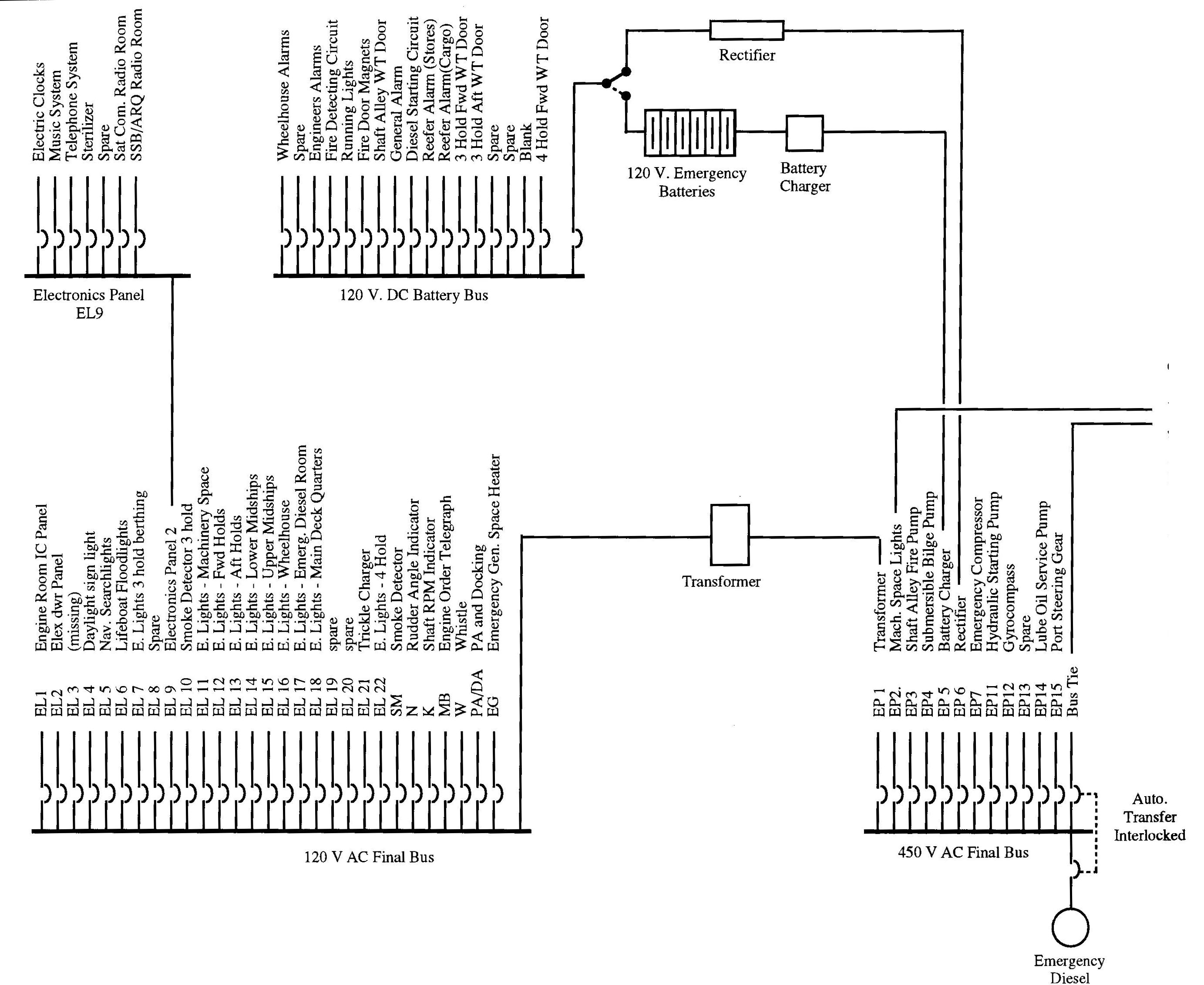
Emergency Electrical Power Distribution System
When the ship is alongside, power can be supplied to the main switchboard from shore, through the shore connection.
The original shore power connection was weather tight 600 ampere shore connection box is located at the after end of the house near the centerline, for supplying 440 volts, 3 phase, alternating current shore power to the main switchboard through a circuit breaker connection to the bus. Later, a 1200 amp connection box on the starboard side of the "B" deck passageway outside the engine room was installed to provide additional shore power capacity for when the ship is tied up in Buzzards Bay..
Provisions are made for synchronizing each main generator with the main bus. Thus, the main generators may be synchronized with the shore power for short periods while changing the load from one power source to another.
The electrical distribution system on board the Patriot State is referred to as an ungrounded distribution system. An ungrounded distribution system has no deliberate electrical connection to ground, ground being the hull of the ship. Its most significant advantage is that accidental contact between one hot line and ground (i.e. a ground fault) does not cause an outage (via circuit breaker tripping due to excessive current). Although a single ground fault on an ungrounded system does not cause an interruption in service, it is important that the fault be located and cleared immediately. If not remedied and a second ground fault occurs on any one of the other two phases, a short circuit current will result. This short circuit current may trip one or more circuit breakers. A double ground fault condition is shown in the next figure.
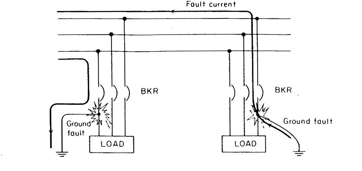
Path of current in an ungrounded distribution system resulting from grounds on two different phases
Ground fault detecting circuits for use in ungrounded systems to indicate the presence of a ground fault are shown below. Sub-figure (b) shows the ground fault detecting circuit on board the Patriot State. Three identical lamps are connected across the three phase line voltage. Each lamp has a resistor in series with it to limit the line current in the event of a single ground fault condition. The junction point of the three lamps is connected to ground (the hull) through a normally closed spring return switch. A low resistance ground fault on any one of the three hot lines will cause its respective lamp to burn dimly or even go out, (depending on the severity of the ground fault), with the other two lamps burning more brightly; with no ground faults all three lamps will be dim. The three lamps should have identical wattage ratings and a voltage rating equal to the line voltage. The normally closed spring return switch provides a means for comparing the normal and ground fault indications. Opening the spring return switch disconnects the ground fault detection circuit from the hull of the ship and all three lamps should return to a dim status.
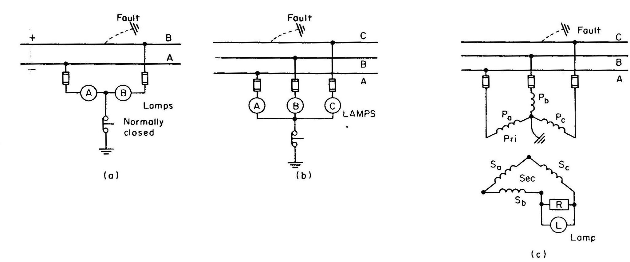
Ground Detection for ungrounded distribution systems: (a) Single Phase or DC (b) Three-phase, low voltage (c) Three-phase, high voltage
Accidental ground faults should be repaired as soon as possible, for even one ground fault has a bad effect on the insulation. A single ground fault doubles the electrical stresses on the remaining insulation, thus increasing the possibility of an insulation breakdown in the other two phases. The doubled electrical stresses cause twice the electron leakage through the insulation, hastening the deterioration and shortening its life. This is illustrated in Figure 3. The insulation resistance between each conductor and ground is R ohms. With 120 volts applied between the two conductors, the voltage between each conductor and ground is 60 volts. However, if one conductor has a ground fault condition, as indicated by the dotted line in Fig. 3b, the voltage difference between the other conductor and ground will rise to 120 volts. Hence the voltage stress on the insulation of the ungrounded conductor is doubled, and if a weak spot in the ungrounded conductor's insulation causes it to rupture, a short circuit will result.
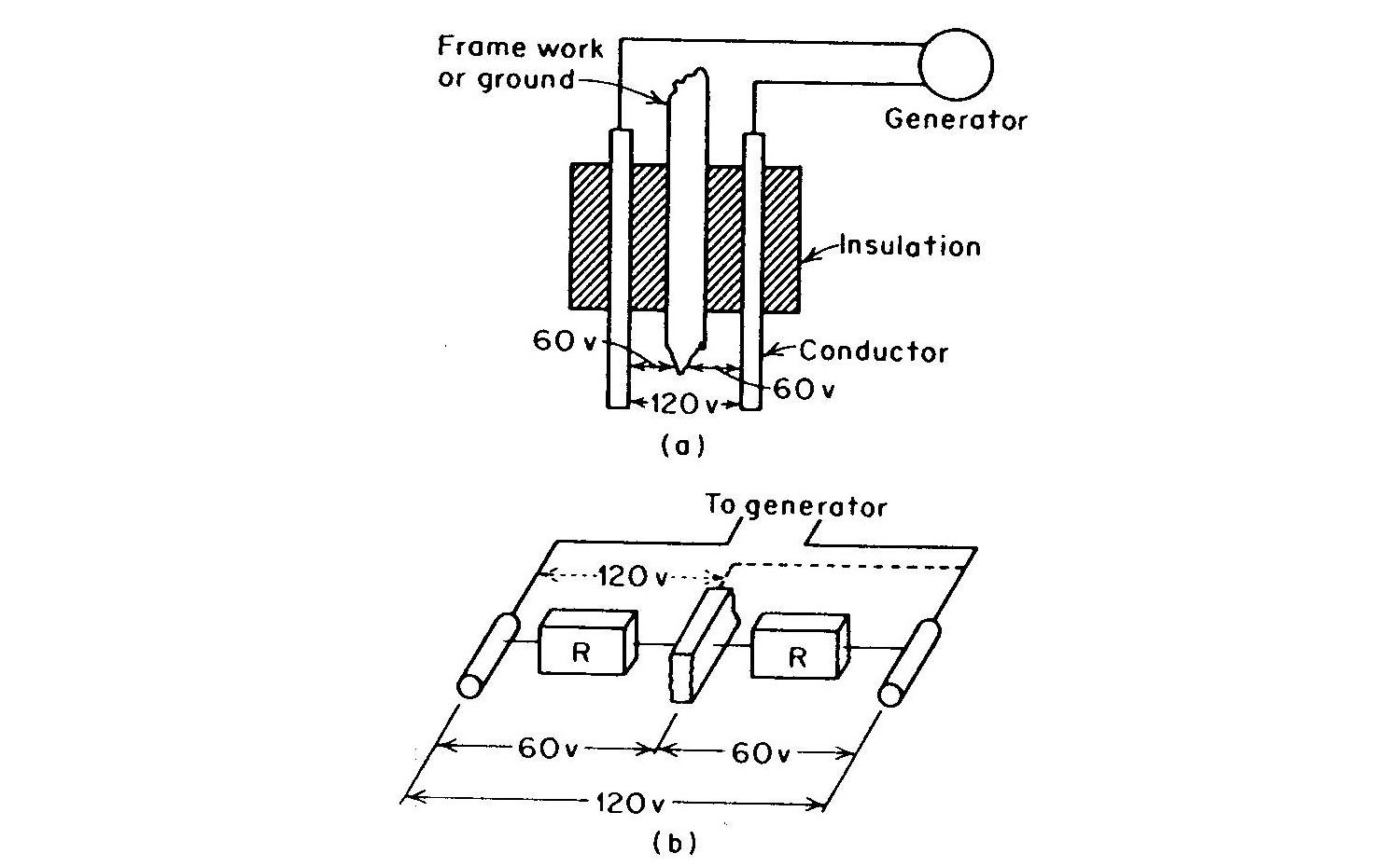
Distribution of Voltage between Conductors and Ground
Troubles in ungrounded distribution systems usually manifest themselves by failure of a device to operate, an indication on the ground fault detection apparatus, smoke, or the overheating of a cable. Shorts and opens are relatively easy to locate and are indicated by blown fuses, tripped breakers, and voltage failure respectively. Grounds faults on the other hand, unless accompanied by a short or an open, are generally located by the process of elimination. The ground faulted circuit may be determined by opening breakers on the distribution panel one at a time, until the ground-detecting device on the switchboard indicates normal. Closing each breaker before opening the next keeps the interruption of service to a minimum. The opening of breakers supplying vital auxiliaries should be avoided until standby equipment is placed in operation. If this procedure fails either the ground fault is in the generator or more than one ground is present.
Multiple grounds faults may be located by opening the breakers one at a time, and leaving them open until the ground fault detecting lights indicate normal. Then with the ground faulted breaker left open, the other breakers should be closed until another ground fault is indicated. A ground fault in a generator may be identified by transferring the load to another machine and tripping the suspect machine from the line. If the generator has a ground fault ,tripping it should return the ground detecting lights to normal. Tracking down the actual location of the ground faulted conductor is done best with a megohmmeter. When doing so the breaker to the grounded faulted circuit should be blocked open, and a "Do Not Close-Man Working On Line" sign hung over the breaker. Figure 4 illustrates the megohmmeter method for tracking down a ground that may be in the supply cable, starter, motor cable, or in the motor itself. Always insure the circuit is dead before checking the insulation resistance. The supply cable may then be tested by applying a megohmmeter between the metal framework of the motor and the supply cable. A zero reading on the megohmmeter indicates a ground fault condition.
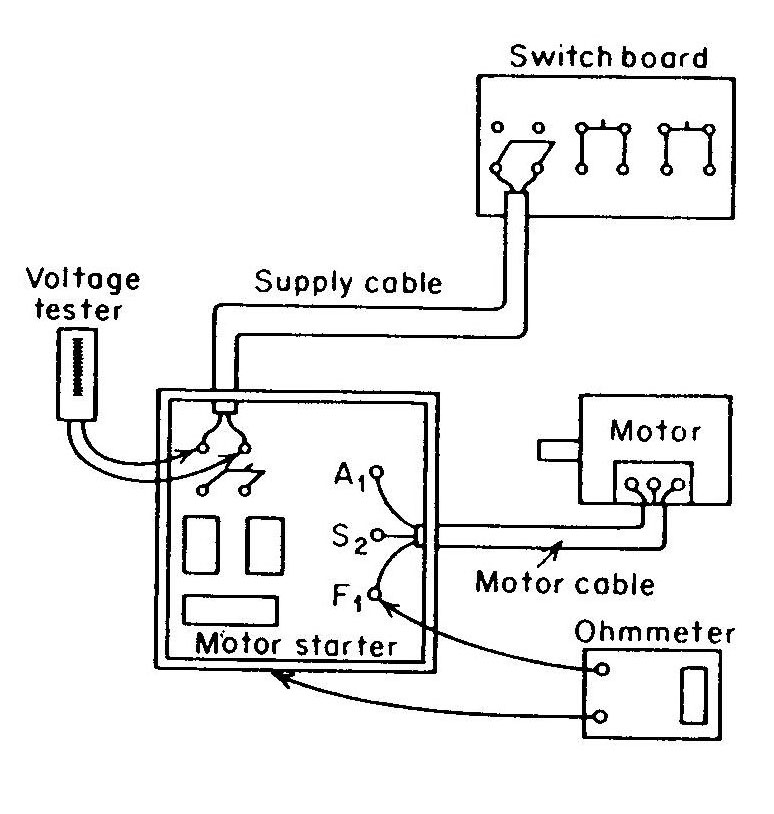
Tracking down a ground by the process of elimination
The 120 volt final bus provides the electrical distribution for lighting, appliances and also to the 120 volt electrical outlets (plugs). The pronged end of the outlet is the grounding connection . This insures that any appliance, power tool and anything else that plugs into the pronged end of the outlet is securely grounded to the ship's hull. This provides ground fault protection from high or low resistance ground faults in 120 volt a.c. appliances by providing a safe path for electricity in the event of a ground fault. This grounding circuit also allows the ground fault detecting equipment to detect the ground fault at the switchboard.
All electrical equipment and outlets on board ship are securely grounded to the hull, so that in the event of ground faults, the ground lamps on the switchboard will indicate the fault. although all the electrical equipment on board is securely grounded to the hull, this type of distribution system is referred to as an ungrounded electrical distribution system. This is due to the fact that resistors in series with the ground detecting lamps prevent short circuit current, subsequent breakers tripping and power outages. The reason for this is obvious, you want a warning before loss of vital equipment. The ungrounded distribution system gives you this warning.
Direct comments to William Haynes whaynes@maritime.edu
Mon, Jul 1, 1996
TSPS Engineering Manual ©1995 Massachusetts Maritime Academy