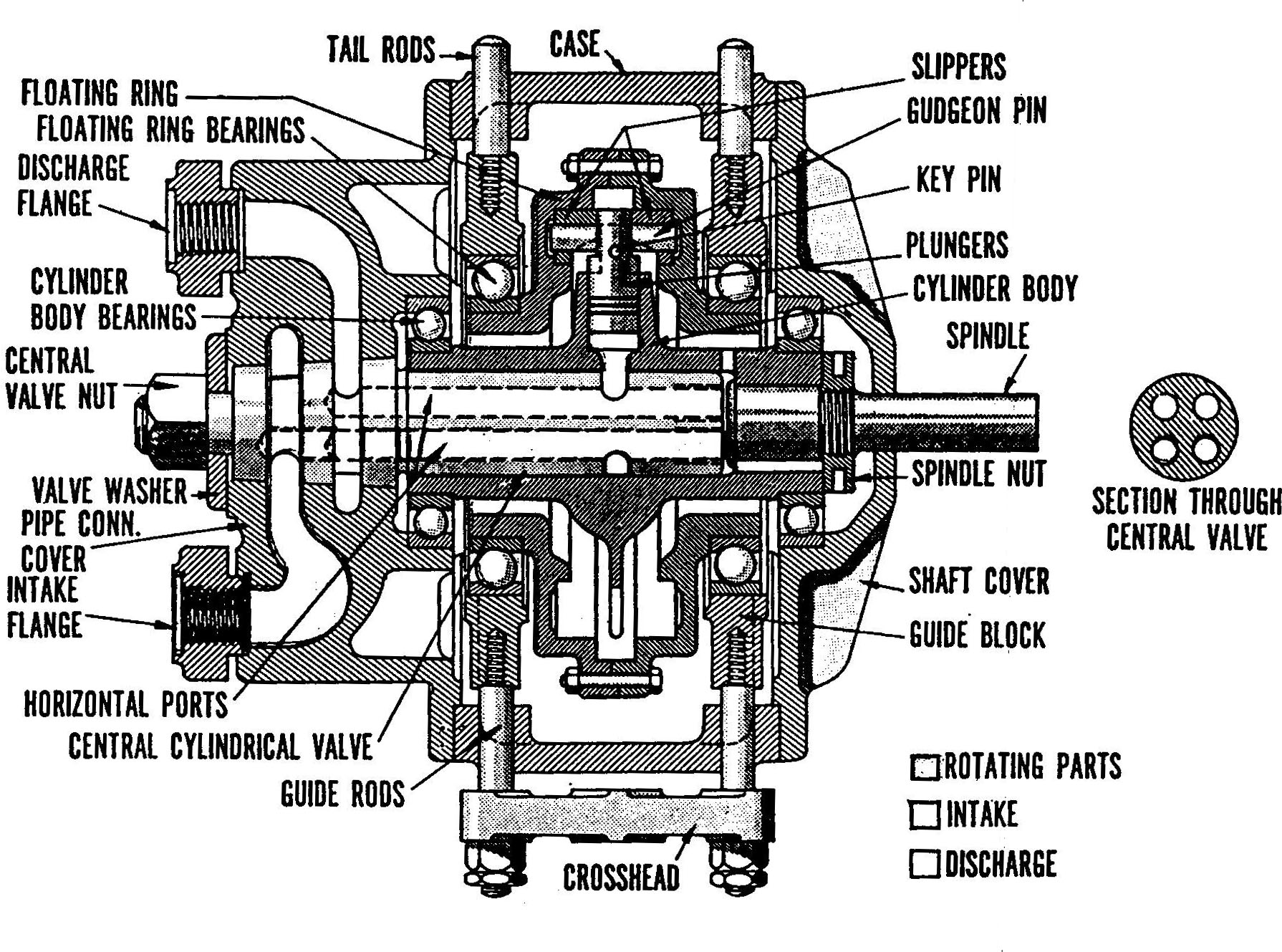
Variable Stroke Radial Piston Pump, Cross Section
Patriot State was the training ship of the Massachusetts Maritime Academy from 1986 to 1998.
Two variable stroke radial piston pumps are provided to supply oil under pressure to move the rams. The capacity of the pump and direction of flow are variable and permit the rudder to be moved in either direction at any speed up to the maximum available.
The operation of the radial piston pump is illustrated in the figure on the next page. The pump consists of a central valve which remains stationary, a cylinder body which revolves around the central valve and contains the cylinders in which the pistons operate. A rotor which houses the reaction ring of hardened steel against which the piston heads press, and a floating ring which is connected to a crosshead and is used to control the length of the piston stroke. The floating ring does not rotate but houses and supports the rotor, which does rotate due to the friction set-up by the sliding action between the piston heads and the reaction ring. The cylinder body is keyed to the drive shaft.
Referring to view (a), assume that space (x) in one of the cylinders of the cylinder body contains liquid and that the respective piston of this cylinder is at position (1). When the cylinder body and piston are rotated in clockwise direction, the piston is forced into its cylinder as it approaches position (2) and then position (3). This action reduces the volumetric size of the cylinder and forces a quantity of liquid out of the cylinder and into the outlet ports in the upper half of the central valve. This pumping action is due to the fact that the rotor, in the floating ring, is off centered in relation to the center of the cylinder body as the piston moves from position (3) to position (4), the open end of the cylinder passes over the solid part of the central valve; therefore, there is no intake or discharge of liquid during this time. As the piston and cylinder move from position (4) to position (5) and position (6), centrifugal force causes the piston to move outward against the reaction ring of the rotor. During this time, the open end of the cylinder is open to the intake side of the central valve and, therefore, fills with liquid. When the piston is at position (6), the open end of the cylinder is against the solid side of the central valve and no intake or discharge of liquid takes place. When the piston reaches position (1), another discharge of liquid begins. Alternate intake and discharge continues as the rotor rotates about its axis - intake on one side of the central valve and discharge on the other as the piston slides in and out.
Notice in view (a) that the center point of the floating ring is different from the centerpoint of the cylinder body. It is the difference of these centers that produces the pumping action. If the rotor is moved so that its centerpoint is the same as that of the floating ring, as shown in view (b), there is no pumping action since the piston does not move back and forth in the cylinder as it rotates with the cylinder body.
The flow in this pump can be reversed by moving the floating ring; and therefore the rotor to the right so that the relation of the centers of the floating ring and the cylinder body is reversed from the position shown in view (a). View (c) shows this arrangement. Liquid enters the cylinder as the piston travels from position (1) to position (3) and is discharged from the cylinder as the piston travels from position (4) to position (6).
In the illustrations, the floating ring is shown in the center, the extreme right, or the extreme left in relation to the cylinder body. The amount of adjustment in distance between the two centers determines the length of the piston stroke, which controls the amount of liquid flow in and out of the cylinder. Thus, this adjustment determines the displacement o the pump; that is, the volume of liquid the pump delivers per revolution. This adjustment may be controlled in different ways. Manual control by means of a trickwheel connected through a differential gear train to the crosshead connected to the floating ring is one of the simplest. Some ships utilize a hydraulic telemotor system which is a hydraulic device in which a sending telemotor actuated by the movement of the ship's wheel in the pilot house sends a hydraulic signal to the receiving telemotor in the steering engine room. The receiving telemotor was connected to the crosshead of the Hue Shaw pump, the movement of which put the pump on stroke or took it off stroke.
Instead of a telemotor, the T.S. Patriot State utilizes an electrical signal from the dual control gyro pilot steering stand to activate a solenoid valve which allows hydraulic fluid from the compensated hydraulic pump unit to move the piston rod of the linear hydraulic power unit. The power unit is connected through a differential gear train to the crosshead of the Hele Shaw pump. Movement of the crosshead controls the pumps pumping condition.
A variable stroke Hele Shaw pump is designed with an odd number of pistons, i.e., 7, 9, 11, etc. This is to insure that no more than one cylinder is completely blocked by the solid part of the central valve between suction and discharge ports. If there were an even number of pistons spaced evenly around the cylinder body (for example, eight) there would be occasions when two of the cylinders would be blocked by the solid part of the central valve between suction and discharge ports, while at other times none would be blocked. This would cause three cylinders to discharge at one moment then four at then next, causing pulsation in flow. With an odd number of pistons spaced evenly around the cylinder block, only one cylinder is completely blocked by the solid part of the central valve at any one time. This reduces pulsation in the discharge.
Variable Stroke Radial Piston Pump, Cross Section
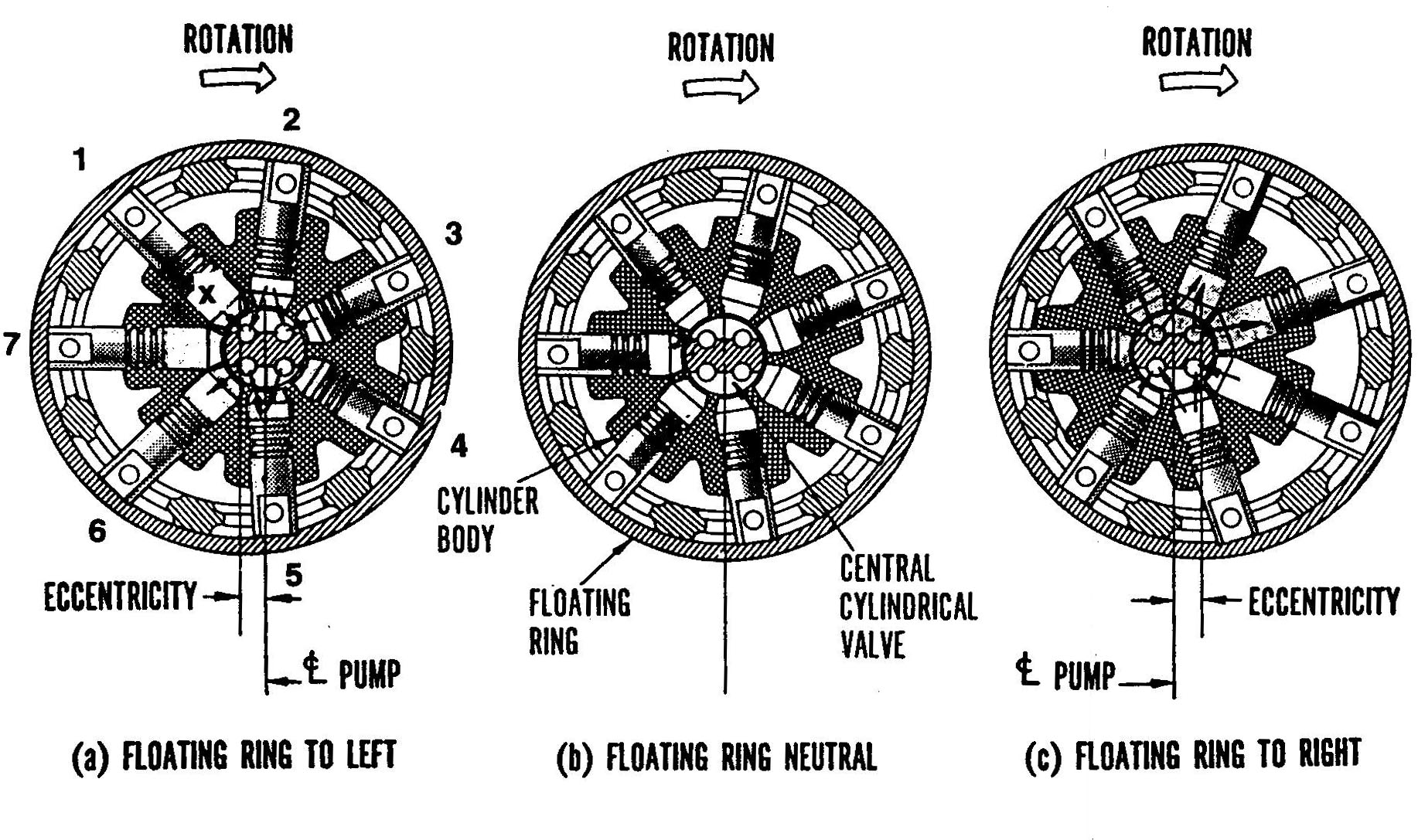
Variable Stroke Radial Piston Pump, Operation
Some of the principal parts of the radial piston pump are described in more detail in the following paragraphs.
Central Valve - the central valve is a round bar which serves as a stationary shaft around which the cylinder body rotates. The central valve has four holes bored from one end lengthwise through part of its length. Two holes serve as the intake and the remaining two as the discharge. Two slots are cut in the side of the shaft so that each slot connects two of the lengthwise holes. The two slots are in line with the cylinders when the cylinder body is assembled on the central valve. One of these slots provides the path for the liquid to pass from the cylinders to the discharge hole bores into the central valve. The other slot connects the two inlet holes to the cylinders during the entrance of liquid. The discharge holes are connected through appropriate fittings to a discharge line so that the liquid can be directed into the system. The other pair of holes are connected to the inlet line.
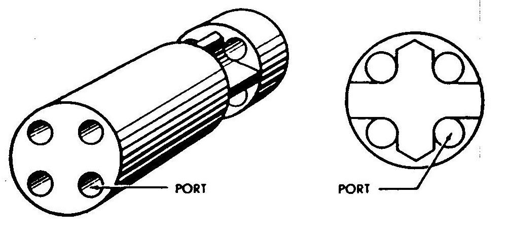
Central Valve
Cylinder Body - One type of cylinder body is illustrated below This is a cylindrical-shaped block of metal with a hole bored through the center to accommodate the pintle. The cylinder holes are bored from the outer edge of the block to the center hole and are spaced as equal distances around the circumference of the block. Both the cylinder holes and the center hole are very accurately machined so that liquid loss around the pistons and the central valve is kept to a minimum.
Radial Piston Pump, Central Body
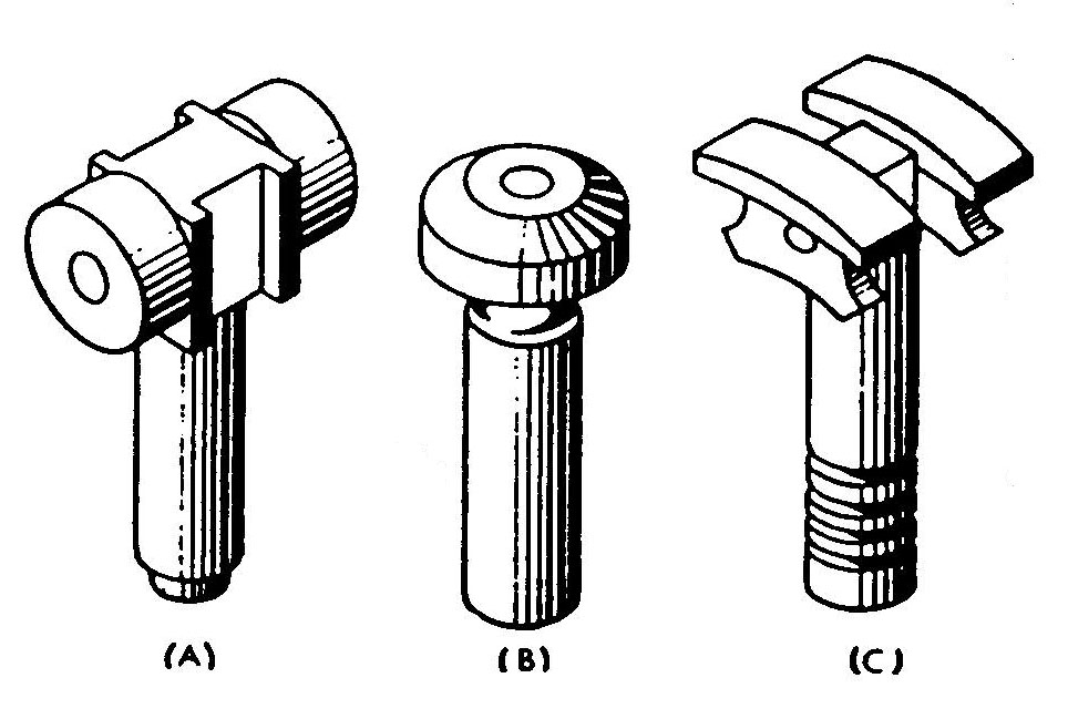
Pistons - Like cylinder bodies, pistons are manufactured in different designs. Some of these designs are illustrated below. View (A) shows a piston with small wheels that roll around the inside surface of the rotor. View B shows a piston in which the conical edge of the top bears directly against the reaction ring of the rotor. In this particular design, while the piston moves back and forth in the cylinder, it will rotate about its axis, so that the top surface will wear uniformly. View (C) shows a piston attached to curved plates. These curved plates, sometimes referred to as curved shoes or slippers, bear against and slide around the inside surface of the rotor. Like the cylinder walls, the sides of the pistons are accurately machined to fit the cylinders, so there is a minimum loss of liquid between the walls of the cylinders and the pistons. No provision is made for the use of piston rings to help seal against leakage.
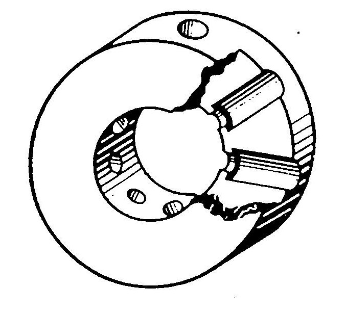
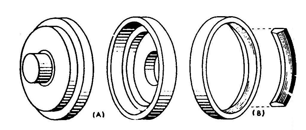
Rotor and Floating Ring- Here again, the design may be different from pump to pump, as shown in figure 8-22. The rotor consists essentially of a circular ring, machine finished on the inside, against which the pistons bear. The rotor rotates within the floating ring which can be shifted from side to side to control the length of the stroke of the pistons. The floating ring has two pairs of machined surfaces on the exterior so that it can slide in tracks in the pump case. The sliding motion is controlled by any means covered earlier in this chapter.
These parts, together with the drive shaft, constitute the main working parts of the radial piston pump. The drive shaft is connected to cylinder body and is driven by an outside force such as an electric motor.
The prime movers for the Hele Shaw radial piston pumps aboard the T.S. Patriot State are 40 HP, 440V, 60 CPS electric motors manufactured by Stearns Electric Corp. The pumps discharge to the high pressure piping system and are mounted on a common bedplate, which incorporates a built-in tank for the active system and oil storage.
Direct comments to William Haynes whaynes@maritime.edu
Mon, Jul 1, 1996
TSPS Engineering Manual ©1995 Massachusetts Maritime Academy