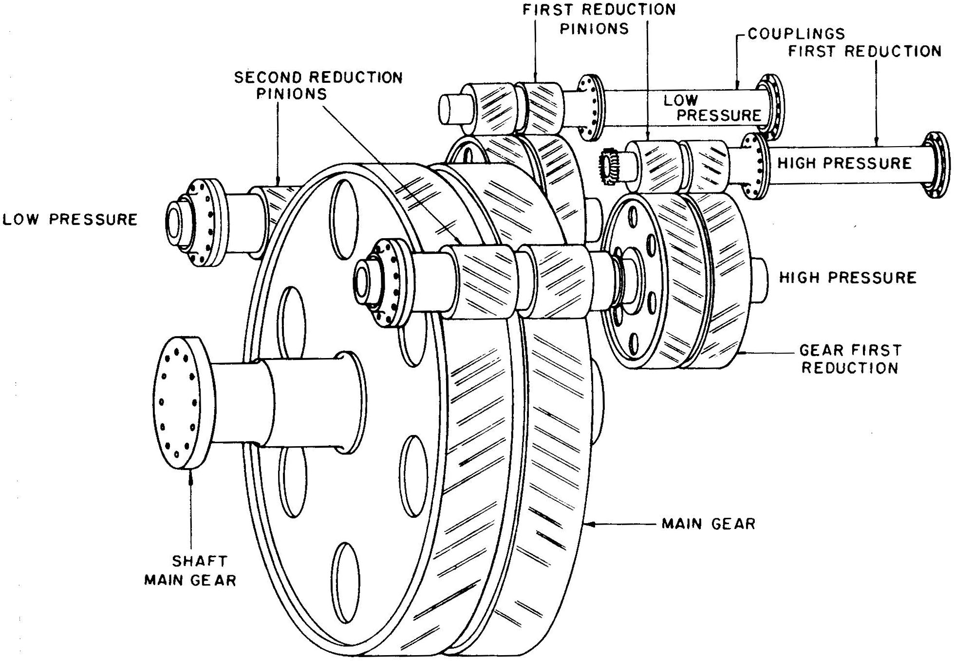
Main Reduction Gear: General Arrangement
Patriot State was the training ship of the Massachusetts Maritime Academy from 1986 to 1998.
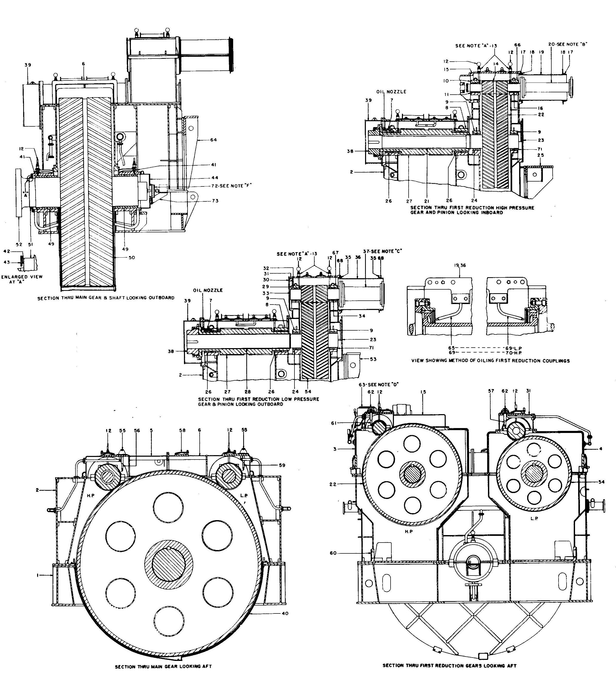
The reduction gear unit is of the articulated, double helical, double reduction type. In this design, the three gear trains; high pressure first reduction low pressure first reduction and second reduction are each contained in a separate portion of the gear housing. The first reduction elements are located at the forward end of the unit, ahead of the main gear wheel where they are attached to the turbine. Connection between the first and second reductions is made by means of quill shafts which extend through the hollow, bored low speed pinions and attached at the after ends. The utilization of quill shafts and couplings in this manner effectively divides the gear elements into three component parts, each of which can be handled separately. Quill shafts are also used between the first and second reductions to obtain flexibility.
The use of double helical gears as opposed to a single reduction gear, reduces shock in the gear train. Since the double helical gears have two sets of teeth at complimentary angles, end thrust is prevented
Main Reduction Gear: General Arrangement
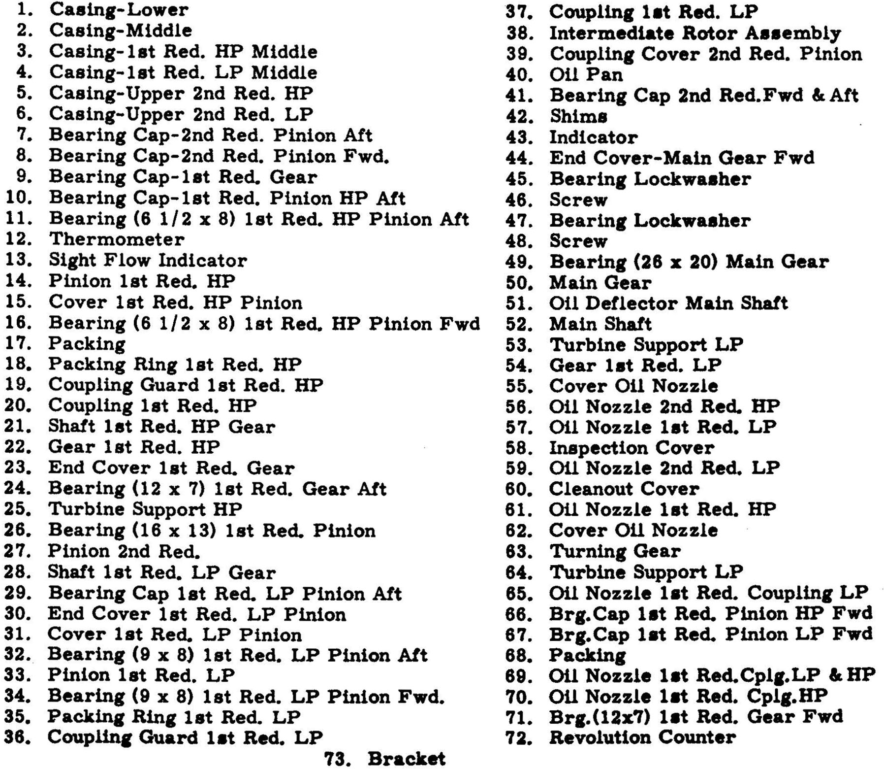
Main Reduction Gear: Assembly Legend
Main Reduction Gear: Assembly
Main Reduction Gear: Rotor Assembly, showing quill shaft
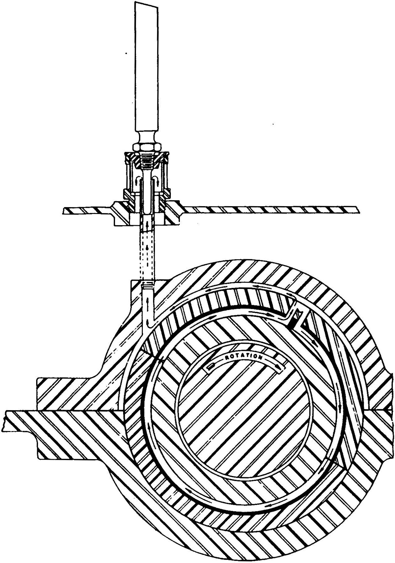
Each rotor, gear and pinion is supported by two sleeve bearings of cylindrical type. The bearing shells are made of steel, lined with Babbitt and split in halves. They are arranged so that the bottom halves can be rolled out without removing the shafts, after the weight of the shafts has been taken off the bearings by a lifting device. Locking screws are provided to prevent rotation of the bearing shells in the casing. A positive indication of lubrication is provided by the sight flow indicators.
Both turbines and the reduction gear are also provided with thrust bearings to prevent axial motion of the turbines and gears. Axial position indicators are provided to permit the operator to monitor turbine rotor position and thrust bearing wear.
The propeller thrust in both ahead and astern directions is absorbed by a pivoted, segmental type thrust bearing located aft of the second reduction. The main thrust bearing is mounted in its own casing and sits aft of the main reduction gears. The housing is supported by two wide flanges at the centerline level and by-and-by an integrally cast beam underneath in the longitudinal vertical plane.
The bearing is designed for a unit thrust of 300 psi and a propeller thrust of 255,000 pounds which corresponds to 18,500 shaft horsepower. Lubrication of the thrust bearing is from the main lubricating oil system.
The main thrust bearing is of the Kingsbury thrust type. It is composed of eight thrust shoes on each side of the thrust collar; which is an integral part of the thrust shaft.
The thrust bearing is flooded with lubricating oil to provide lubrication for all its surfaces. The lube oil is supplied from the main engine sump. The oil is cleaned and maintained along with all the oil in the main lubricating system. Seal rings are provided at the ends of the thrust space as well as the ends of the thrust housing; to prevent the escape of oil out along the shaft.
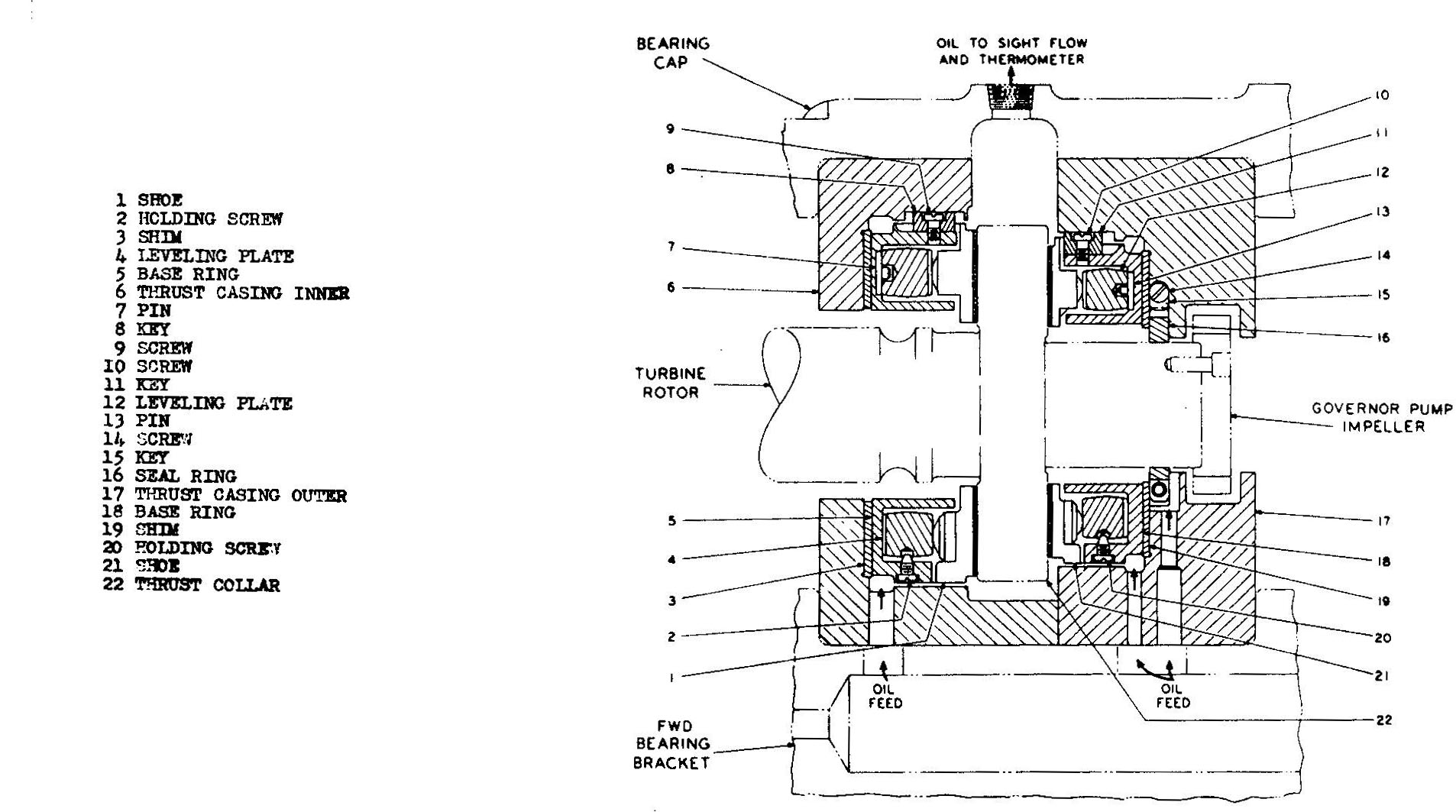
Thrust Bearing, High Pressure Turbine
Main Engine Bearing Lubrication

H.P. Turbine Rotor Position Indicator
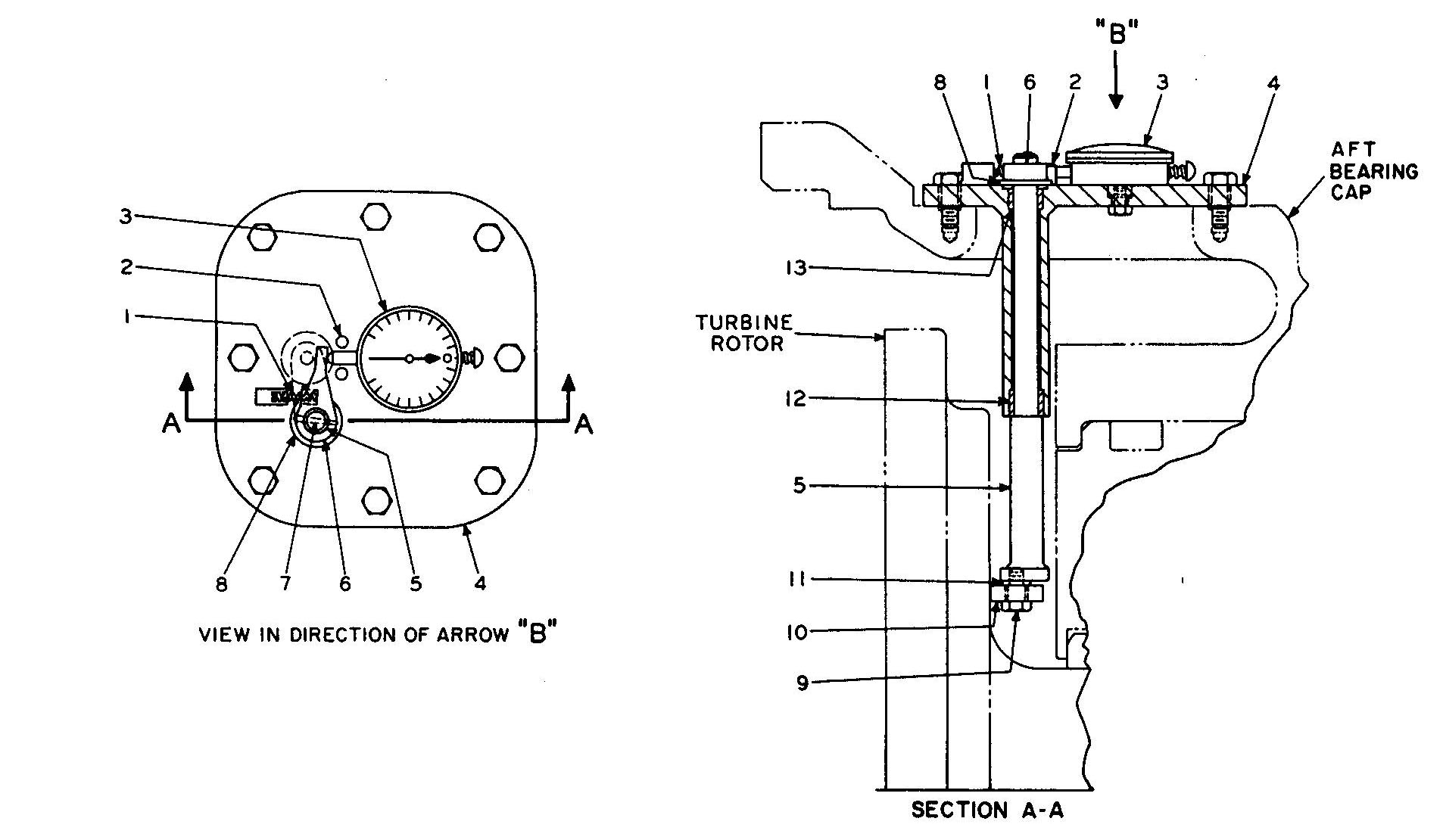
L.P. Turbine Rotor Position Indicator
The shaft turning gear is a motor-driven, double-reduction worm gear assembly, provided to serve as a driving machine for
The turning gear is designed to turn the propeller shaft one revolution in approximately ten minutes. The motor, driving through a flexible coupling, delivers power and rotation to a first-reduction worm and gear. The first- reduction worm gear is mounted on one end of the second-reduction worm which transmit torque to the second- reduction worm gear. The second-reduction worm shaft is equipped with a sliding spline which freely engages and disengages with a spline on the aft end of the first-reduction, high-pressure pinion. This sliding coupling is moved axially by a shifting lever. This lever is secured in either the Engaged or Disengaged position by means of a push button which may be locked to secure the lever. Nameplates marked Engaged and Disengaged are attached to the casing to indicate the position of the spline.
Caution: The turning gear MUST be disengaged before steam is admitted to the turbines!
The turning gear is equipped with a locking device for the purpose of locking the propulsion equipment and propeller shaft against rotation while the ship is being towed. The propeller shaft locking device is located on the second reduction worm gear shaft opposite the engaging spline.
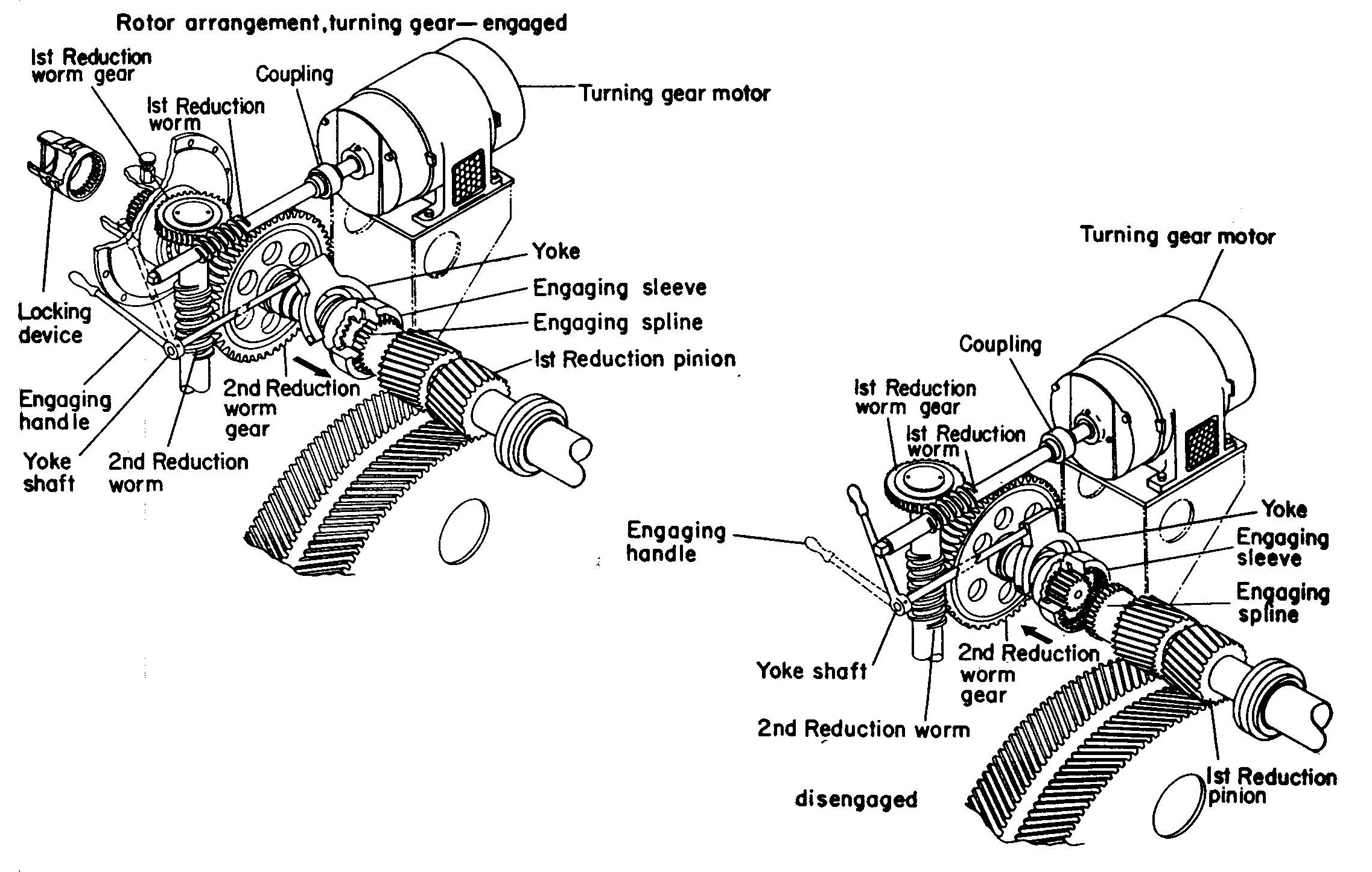
Jacking Gear

Jacking Gear Assembly
The propeller shaft is of solid forged steel, American Bureau of Shipping, Grade No. 2. The shaft is approximately 32' 0" long with a diameter of 24.25 inches and fitted with centrifugally cast sleeves of composition "M" in way of the bearing.
The seven sections of line shafting are solid forged steel, American Bureau of Shipping, Grade No. 2 with coupling flanges forged integrally. Number of sections and dimensions of the line shafting are:
Ten line shaft bearings of the ring oiled type are provided. Each bearing is designed to carry a maximum bearing load of 47.5 psi.
The stern tube bearing is water lubricated. The bearing consists of a bronze bearing bushing which retains a number of bearing contact elements that are made of lignum vitae wood. A sleeve is installed on the shaft to provide a corrosion-resistant contact surface. Lignum vitae absorbs water and consequently tends to swell. Swelling must be considered in the design. Lignum vitae must be kept damp at all times as it will otherwise become dry and crack.
The propeller is four bladed, solid, right-hand type made of nickel aluminum bronze, 22'0" in diameter with an effective pitch of 18'-10.5". Tensile strength of the material is 80,000 psi minimum. Elongation in two inches is 15%. The propeller is statically balanced and the centrifugal force from any unbalance does not exceed one percent of the propeller weight when it is rotating at the maximum rpm.
The rudder is the semi-balanced type, of streamline form with welded double plate construction. Positive hardover stops are provided at 38° travel on each side. The area of the rudder is approximately 245 square feet.
Direct comments to William Haynes whaynes@maritime.edu
Mon, Jul 1, 1996
TSPS Engineering Manual ©1995 Massachusetts Maritime Academy