Turbogenerator Rotor
Patriot State was the training ship of the Massachusetts Maritime Academy from 1986 to 1998.
The primary electrical power requirements of the Patriot State are met by three, alternating current, geared steam turbine, ships service generators. All three ships service generators are located in the main machinery space, between frames 118 and 124 on the starboard side of the auxiliary machinery flat. All three generators are identical, all having the same characteristics and ratings. Each of the ships service generators are rated to produce 750 kw continuous, 450 volts, 0.8 power factor, 60 cycle, 3 phase electrical power.
The three ships service generators also have the same overload ratings. Each generator is capable of operating at a 25% overload (938 kw) for a period of two hours without overheating. Also, the design back pressure for auxiliary turbines, that drive the ships service generator, is 28" hg vacuum. But there is no loss of normal generator capacity with a back pressure as high as 20" hg vacuum.
The three ships service generators are arranged for individual, or parallel operation. Provisions are also made for the ships service generators to be paralleled with shore power. This will facilitate the transfer from shore power to ships service generators. During parallel operation of the ships service generators, any two are capable of supplying the maximum sea or port load. The third ship service generator is therefore free from maintenance or available as a standby unit.
Type:
    DRV-618M, 6-stage   11108/2300 RPM
Rating:
    Continuous  750kW, 0.8PF, 450 volts
                60 cycle 3 phase AC
                1200 RPM
    Overload    25% for two hours
Rated Steam Condition:
    Inlet steam pressure    600 psig
    Initial steam pressure  900° F.
    Exhaust pressure        2" Hg abs.
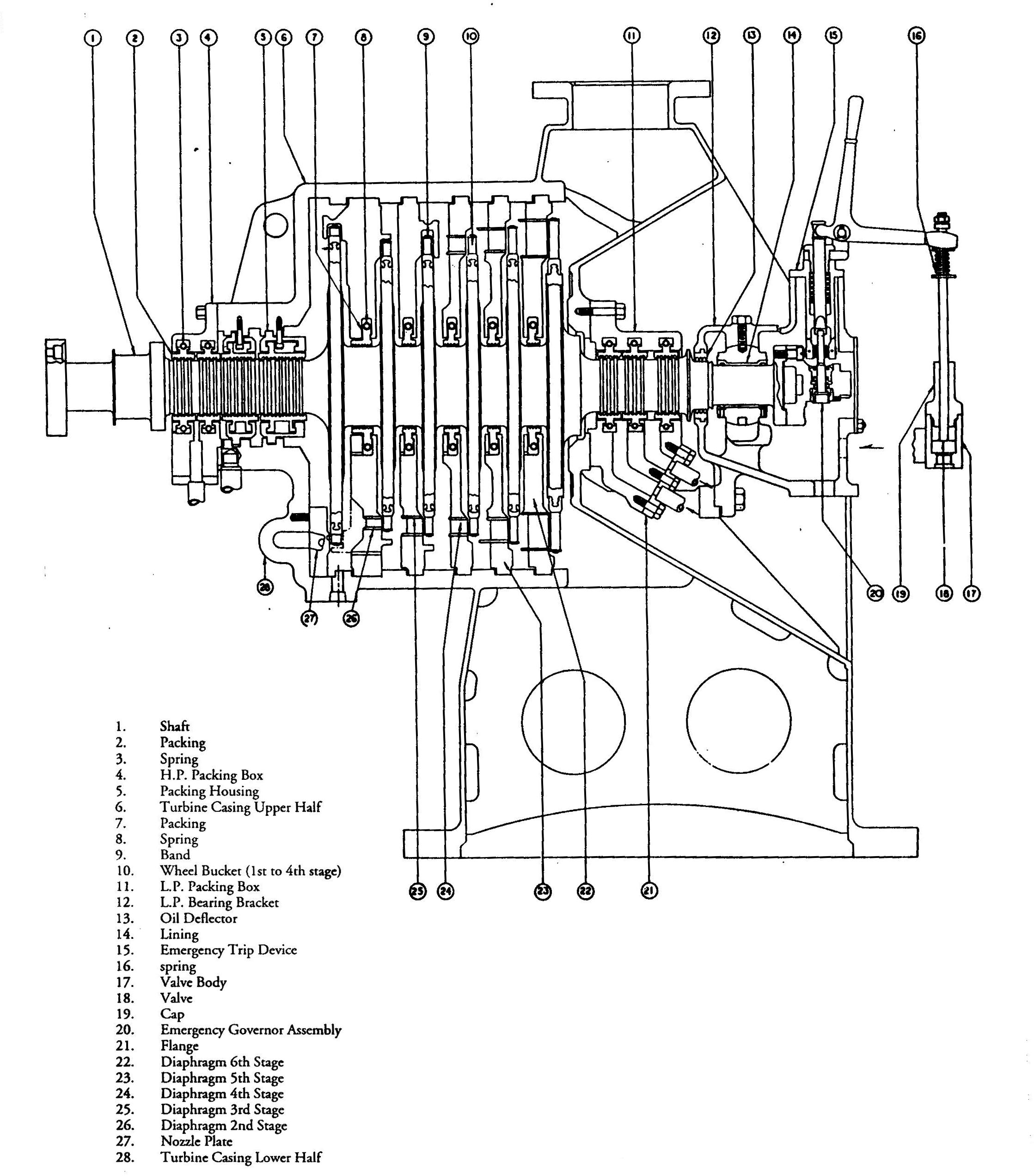
The turbine and quill shaft of the gear pinion are rigidly connected. The pinion and turbine shaft are flexibly coupled with a dental type coupling. The turbine shaft and the gear pinion are supported by four bearings, three in the reduction gear casing and one at the exhaust end of the turbine. The gear end of the turbine shaft is supported by one of the bearings in the gear casing.
The exhaust end of the turbine casing is carried by flexible standards mounted on the structural steel base. These supports provide axial flexibility, thereby, permitting the turbine casing and shaft to expand with temperature change in the direction parallel to the shaft. The supports are rigid in the direction perpendicular to the shaft. The turbine casing is supported at the high-pressure or gear end by the reduction-gear casing.
Steam enters through a steam strainer and in turn passes through the throttle valve and the controlling valves, then to the first-stage nozzleplate. The steam expands in successive stages from initial pressure to final or condenser pressure.
Turbogenerator Rotor
The two shaft packing boxes are connected into a system that provides means for disposing of any excess amount of steam that leaks past the packing rings and also for supplying sealing steam to prevent leakage of air into the turbine. The two valves in the steam-seal system, if operated properly, permit the maintenance of a sealing pressure of one to two psig at the shaft packing boxes. the steam for gland sealing comes form the auxiliary exhaust system.
Since the turbine is a condensing unit, a vacuum will exist in the entire turbine shell during periods of starting and stopping, and of any other time when the turbine is operating at low load. It is during such times, that sealing steam is required to prevent air leaking into the turbine.
During periods of normal full load, there is enough leakage from the high pressure end to seal the low pressure. Therefore, no sealing-steam is needed.
The bearing supports the low pressure end of the turbine shaft. The gear end of the turbine shaft is supported by the pinion shaft coupling.
The turbine shaft bearing is ball seated for self alignment and is babbitt lined. It is split horizontally to facilitate assembly and is clamped to its seat by a bearing cap.
Oil enters the bearing surface at the horizontal joint where the babbitt is relieved to permit the journal to draw the oil around the shaft in the direction of rotation. The oil passes at through drain holes that are drilled into grooves at the ends of the bearing.
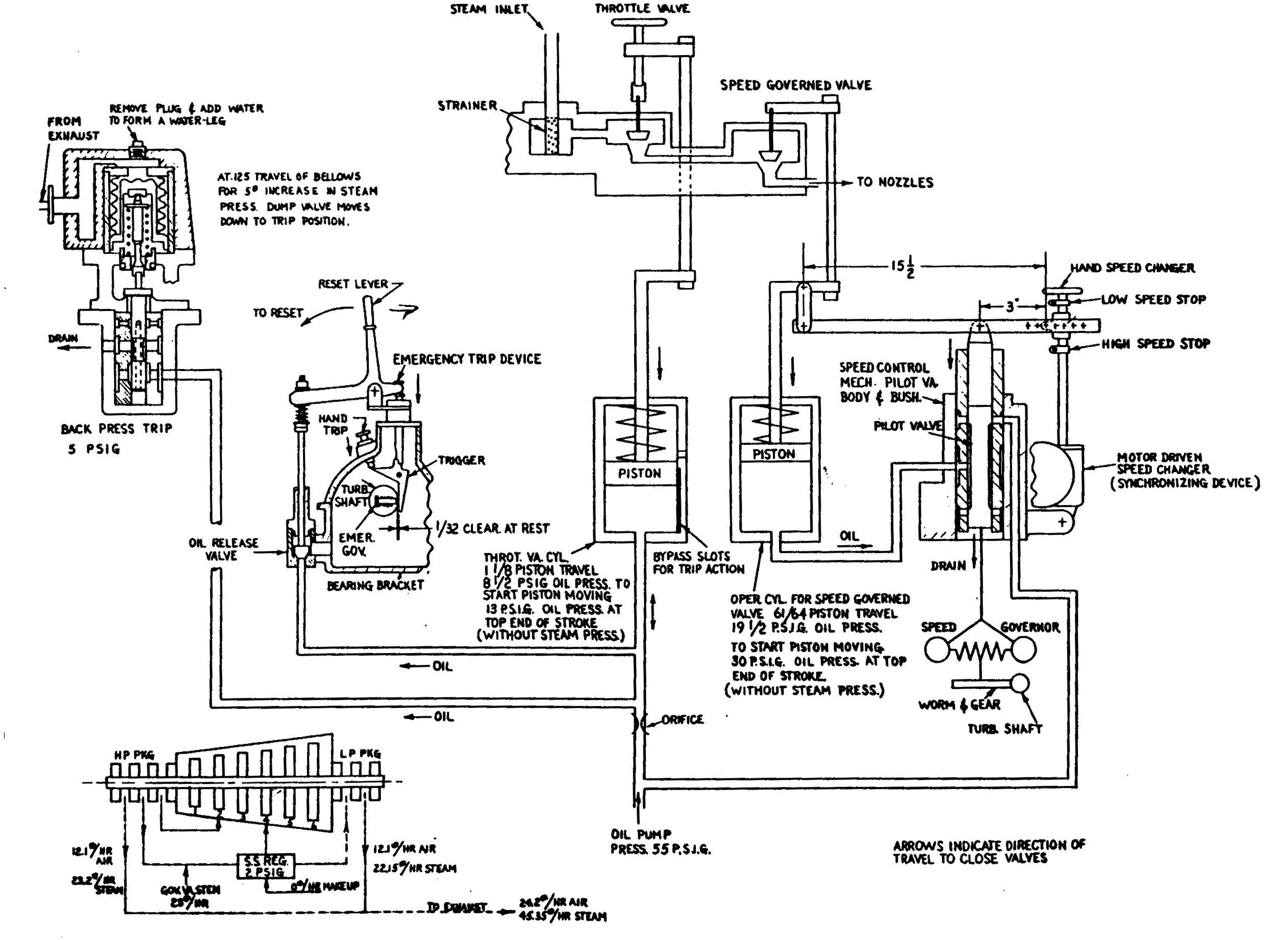
The governing system is designed to automatically maintain narrow speed regulation within the normal operating range under varying load and steam conditions; and provides a means for adjusting the speed and for changing the portion of total load each set is to carry when running in parallel with another set. It also includes an emergency device that closes the throttle valve as the turbine overspeeds.
The governor is driven through a spiral gear, the spiral pinion being directly connected to the shaft of the low-speed member of the reduction gear and thereby driving the governor at a speed that is directly proportional to the speed of the turbine. With an increase in turbine speed, the governor weights move outward and draw the pilot valve downward with a reduction in turbine speed, the weights move in and push the pilot valve upward. It is the position of the pilot valve with respect to the pilot valve bushing that determines the flow of oil to the operating cylinder and therefore the position of the operating valves (governor valves) that admit steam to the turbine. The emergency tripping mechanism forms the connecting link between the emergency governor and the emergency feature of the throttle valve.
When overspeeding occurs, the emergency governor operates and strikes the trigger which turns on its pivot pin and unlatches the trip rod. This rod is pushed downward immediately by the compression spring, swinging the bell crank around its pivot pin.
The bell crank is connected to the valve and stem of the oil release valve. When the bell crank swings about, its axis resulting from the mechanism being tripped by hand by striking the trip button or by the emergency governor, the oil release valve is lifted from its seat in the body allowing oil to drain from under the throttle valve operating cylinder through the pipe line to the valve body and from there into the bearing bracket. This in turn will result in a quick closing of the throttle valve thereby shutting off steam flow to the turbine.
To reset the tripping device after it has operated, first reset the throttle valve. This will raise the cylinder position in the throttle valve operating cylinder above the oil by-pass slots. Reset the tripping device by rotating the bell crank toward the oil release valve until the trip rod is relatched. Now with oil pressure being applied under the piston by means of the hand oil pump, the throttle valve can again be opened allowing steam to pass into the turbine. Care should be taken not to reset the emergency device until the turbine speed has dropped below 7800 RPM, otherwise the emergency governor plunger may hit the trigger.
In addition to the emergency governor, there is a back pressure trip installed on the number 1 and 2 gererators which protects the turbine against excessive exhaust pressure. This device trips at 5 psig exhaust pressure. Each turbine is also fitted with a sentinel valve which relieves at 2 psig exhaust pressure.
Turbogenerator Governor Control System
The shaft driven oil pump draws oil from the tank located in the base of the gear casing and delivers it through the two separate systems to the hydraulic governing mechanism and to the bearing and gear mesh lubricating system. Oil to the lubricating system passes through the oil strainer, manifold and oil cooler.
The hand oil pump likewise draws oil from the tank but delivers it directly to the bearings and hydraulic mechanism.
The normal oil pressure delivered to the governing mechanism should be approximately 55 psig. The normal bearing oil pressure should be approximately 8 psig. A fair running temperature of the return oil is 140-160° F. The maximum temperature rise at ay bearing should not exceed 50° F.
The lube oil strainer is of the duplex type. It consists of two cylindrical strainer baskets connected by a manifold with a plug type valve for delivering the olil through one or the other of the two strainers. While one strainer is in use, the other may be removed for cleaning.
The lube oil system is equipped with a low lube oil alarm. The alarm sounds below 4 psig and is reset at 6 psig.
There is also a low oil presssure switch that activates to open th main generator circuit breaker when the throttle valve hydraulic line pressure drops below 15 psig. This switch resets at 30 psig.
The type 3-387 reduction gear is a single-reduction, single-helical type and reduces the turbine speed of 9963 rpm to the generator speed of 1200 rpm.
Direct comments to William Haynes whaynes@maritime.edu
Mon, Jul 1, 1996
TSPS Engineering Manual ©1995 Massachusetts Maritime Academy