Steering System General Arrangement
Patriot State was the training ship of the Massachusetts Maritime Academy from 1986 to 1998.
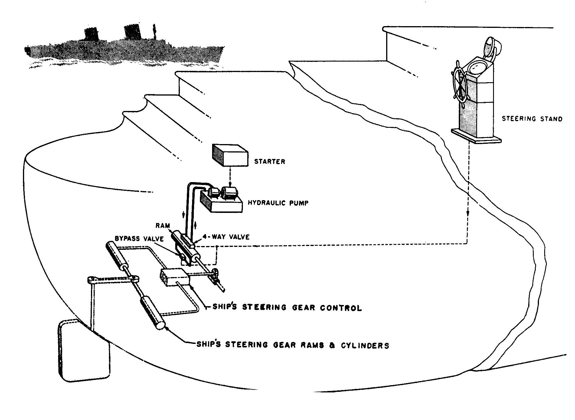
The T.S. Patriot State's steering system is provided to control the rudder in response to helm commands from the bridge. The system consists of the following subsystems. Steering commands are given to the dual-control gyro pilot steering stand located on the ship's bridge. In the steering engine room the commands are received by two linear hydraulic power units and compensated hydraulic pumps and transmitted to two Hele Shaw radial piston pumps. The radial piston pumps direct pressurized hydraulic oil to four hydraulic rams which moves the rudder. Precise control of the rudder position is accomplished by means of a differential gear train and follow-up mechanism. A emergency hand pump is supplied for use in the event of failure of the normal hydraulic system and also for filling and draining the system, and all hydraulic components of the system are tied together with high and low pressure piping systems.
Each of the above mentioned components will be discussed in detail as follows.
Max. Rudder Torque-Ahead at 35° Rudder Angle         3,048,000 in-lbs
Max. Rudder Torque-Astern at 35° Rudder Angle        4,370,000 in-lbs
Max. Pressure-Ahead at 35° Rudder Angle              735 psi
Max. Pressure-Astern at 35° Rudder Angle             1055 psi
Relief Valve Setting                                    1300 psi
Rudder Angle H.O. to H. O.                              70°
Time - H.O. to H.O. (One Power Unit Operating)          2-1/3° per second
Time - H.O. to H.O. (Both Power Units Operating)        4-2/3° per second
No. of Turns for Trick wheel (70° H.O. to H.O.)      9.1
Steering System General Arrangement
The Sperry dual control gyro pilot steering stand provides three types of rudder control: automatic control using the gyrocompass input to maintain the selected heading, hand steering with follow-up, and hand steering without follow-up. Moving the selector switch on the steering stand changes from one type of rudder control to the other.
Regardless of which type of rudder control is utilized, an electric signal is sent to one of two independent electro-hydraulic steering controls located in the steering engine room.
The heart of each automatic steering system (port or starboard) is a potentiometer bridge. Each bridge contains two potentiometers connected in a balanced wheatstone bridge arrangement. One potentiometer of each bridge is called the control potentiometer. It is located in the steering stand, and is positioned by both the steering wheel and the gyro compass which acts on it through a mechanical differential gear train.
The other potentiometer of each wheatstone bridge is called the follow-up or repeat-back potentiometer. It is located in the linear hydraulic power units and controlled by the rudder positioning equipment.
When the control potentiometer is turned by either the steering wheel or by the gyro-compass, a D.C. signal called the course error signal is sent to a solenoid operated directional valve located in each linear hydraulic power unit. The polarity and magnitude of this course error signal indicates the direction and amount of corrective rudder action required.
When the linear hydraulic power unit transmits this rudder order to the radial piston pumps the follow-up or repeat back potentiometer generates a D.C. signal opposite in polarity to the sending signal. When the magnitude of this opposite signal increases to equal the value of the course error signal, the effective instruction to the hydraulic power unit becomes zero, and rudder action ceases. Thus, full follow-up control is provided.
Double cabling connects the steering stand in the wheel house with the hydraulic power units located in the steering engine room. Indicating lights on the steering stand show which system is operating and whether the other system has power available.
The linear hydraulic power unit consists of a double ended hydraulic control cylinder, manifold mounted directional and bypass valves, parallel rack, outside limit switches, inside limit bypass relay and repeat back potentiometer.
The power unit receives electrical signals from the dual control gyro pilot steering stand. In response to these signals, the piston rod is positioned by means of hydraulic fluid delivered under pressure by the Vickers hydraulic pump units. The position rod, in turn, is directly connected through a differential gear train to the floating ring of the radial piston Hele Shaw pump. The amount of travel of the piston is made proportional to the order of the dual control gyro pilot steering control. Also, limits are provided to prevent over-travel of the piston.
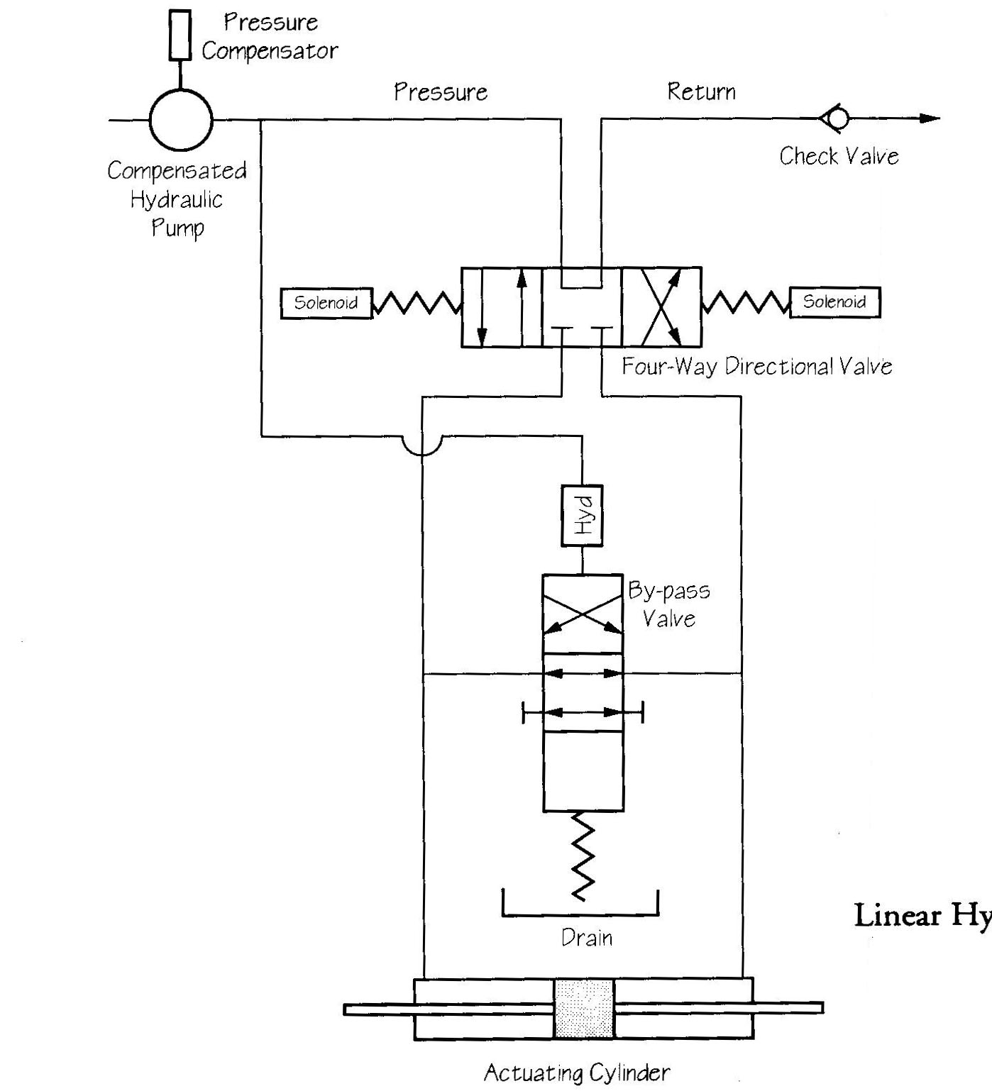
Linear Hydraulic Power Unit
The controlling element of the linear hydraulic power unit is the directional valve which is a solenoid-controlled, pilot-operated, four-way valve. A control signal from the steering stand energizes one of the solenoids in the valve. The solenoid pushes the pilot spool off center, thus porting pilot fluid to offset the main valve spool. This connects one side of the cylinder to the input pressure and the other side to the return line, causing the piston rod and hence the floating ring of the Hele Shaw pump to move. The direction of flow, and thus the direction of the control cylinder movement, will depend upon which solenoid is energized by the steering control.
A parallel rack, which activates the repeat back potentiometer and limit switches is attached to and moves with the piston.
When the piston rod reaches the ordered position, the electrical follow-up signal balances the order signal thereby de-energizing the directional valve.
A bypass valve in the power unit opens when the automatic or hand-electric controls are not in use, allowing oil to flow freely from one end of the power unit cylinder to the other. The ship's steering mechanism can then be operated by separate means with the hydraulic power unit still connected. When the system is energized, hydraulic pressure closes the valve to permit operation. The bypass valve is a hydraulically pressure operated, spring offset four-way valve requiring at least 50 psi pressure for its operation.
Although the bypass valve is a four-way type, its use in this system is limited to either the open or closed position. This is accomplished by blocking one set of ports.
When the system is not in operation, or in the event it should become inoperative, the bypass valve allows oil to flow from one side of the control cylinder to the other so that the piston rod may be moved by an alternate means of steering such as a trick wheel or telemotor. When the pump is turned on to start the system in operation, there is an immediate pressure build-up in the system, due to the check valve. This pressure closes the bypass valve thus allowing the control cylinder to respond to the operation of the directional valve.
The hydraulic power unit contains two pairs of limit switches, designated inside limit switches and outside limit switches. The inside limit switches restrict electrical operation normally to ten °ees of rudder motion in either direction in order to optimize performance when steering automatically. Thus, when an error signal tends to drive the cylinder beyond moderate rudder angles, an inside limit switch opens the circuit to the energized solenoid of the directional valve. The outside limit switches are set to open the solenoid circuit at the hardover rudder positions. Also, these switches are always set to prevent the piston from hitting its mechanical stops. In the hand-electric mode of steering, a relay in the power unit, controlled from the steering stand, closes the circuits across the inside limit switches and allows full rudder up to the angle determined by the outside limit switches.
In normal operation both pairs of limit switches are closed. A control signal is applied to one or the other solenoid of the directional valve from C1 to C+ or from C2 to C+ depending on the direction of the rudder order. The valve operates to port oil in order to move the piston and rod. This also moves the attached rack. The rack drives a pinion which couples through a gear train to the limit switch cam shaft. The gears are chosen at the factory in accordance with the travel distance of the piston rod, so that the cam shaft rotates 270 °ees when the piston rod moves from one position to the other. The cams are set on the shaft during installation for the specific limits required by the particular vessel.
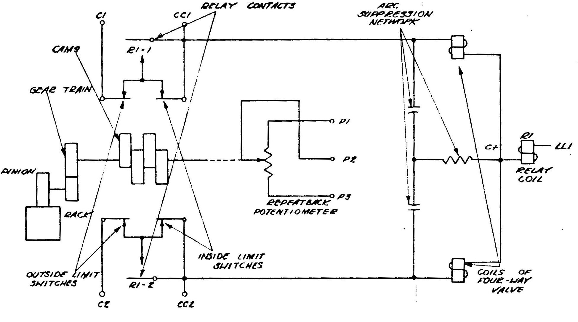
LHPU Limit Switches
When the piston rod has moved sufficiently to produce a rudder angle of about 10 °ees either side of amidships, a cam opens the limit switch in series with the energized valve solenoid and the steering mechanism is held in this position until control current is applied to the other solenoid. If less than 10 °ees of rudder were called for, an inside limit switch would not operate.
In the hand-electric mode of operation, a cam operated switch in the steering stand energizes the inside limit bypass relay in the power unit when a rudder order of approximately 8 °ees is applied by the helmsman. Current applied from LL1 to C+ causes relay coil R1 to close contacts R1-1 and R1-2 across the inside limit switches. Thus, even though cams open the inside limit switches, each circuit from C1 or C2 through a valve solenoid to C+ remains closed. A few °ees short of maximum travel, a cam opens the normally closed snap action outside limit switch there de-energizing the directional valve solenoid and holding the steering mechanism in position until the helmsman orders a return of the rudder toward amidships. Thus the outside limit switches determine hardover rudder and prevent the power unit from driving to its mechanical limits of travel.
The camshaft also drives the rotating wiper of a 5000-ohm wire wound oil-filled potentiometer. This potentiometer is accurately positioned so that when the piston rod is at its mid position, the wiper of the potentiometer is at mid resistance. In this way the potentiometer provides an electrical signal proportional to power unit position for connection into the follow-up circuit of an automatic or hand-electric steering control. In other words, this repeat back potentiometer generates a follow-up signal which is sent to the steering stand. The directional valve solenoid is de-energized when the follow-up signal cancels the control signal.
Both ends of the power unit piston rod carry a clevis, one of which is connected mechanically through the differential gear train to the Hele Shaw rotary pump crosshead. The power unit is capable of transmitting a force of about 6,800 pounds, either as a push or a pull.
Direct comments to William Haynes whaynes@maritime.edu
Mon, Jul 1, 1996
TSPS Engineering Manual ©1995 Massachusetts Maritime Academy