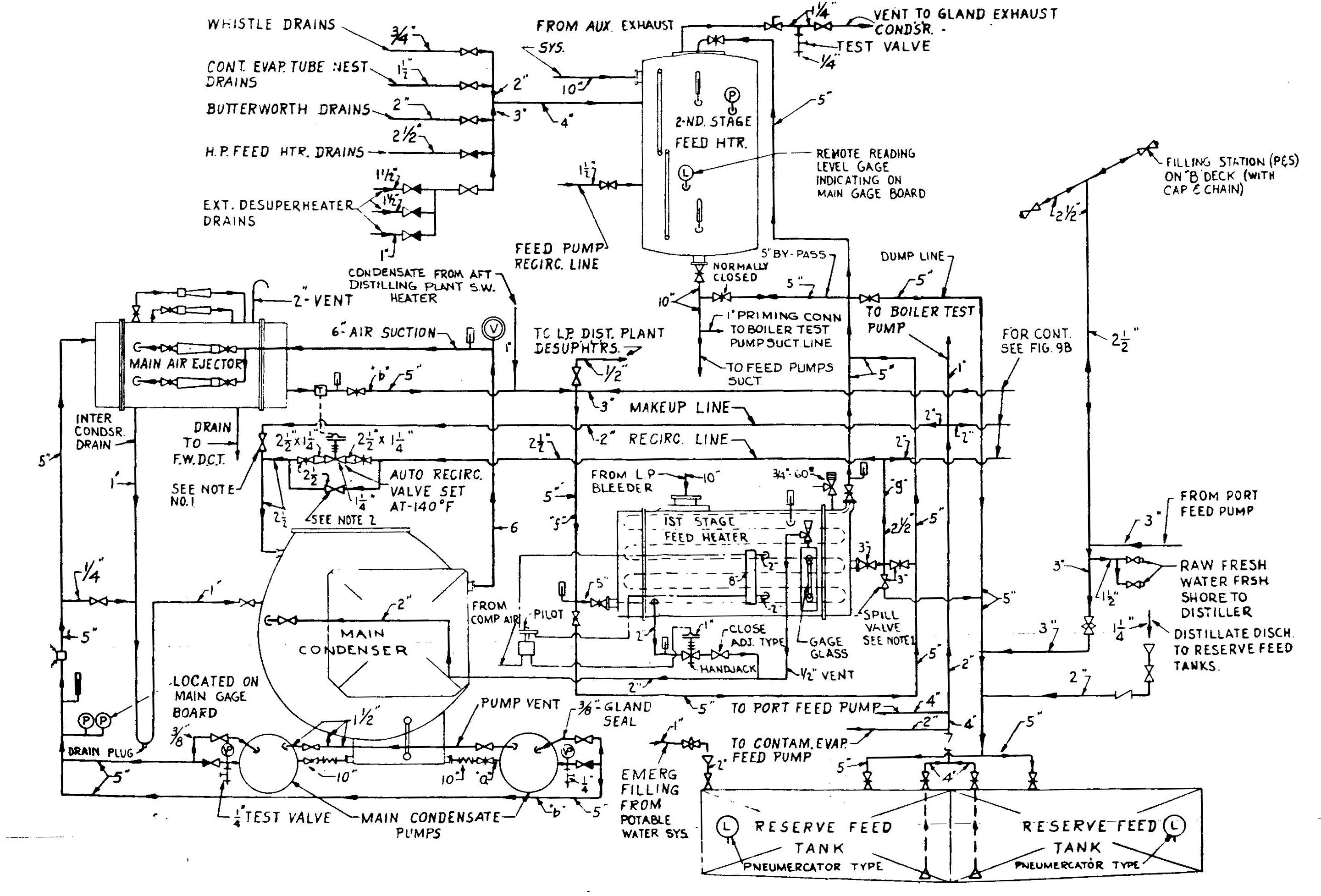
Main Condensate System
Patriot State was the training ship of the Massachusetts Maritime Academy from 1986 to 1998.
The purpose of the main and auxiliary condensate systems is to transfer condensate from the main and auxiliary condensers to the D.C. Heater, and to preheat the condensate to improve plant efficiency. The condensate system includes the condensate pumps, which raise the pressure of the condensate; air ejectors, which establish and maintain the condenser vacuum; and the first and second stage heaters, where condensate preheating takes place.
Main Condensate System
The main condenser is a single pass condenser capable of condensing 95,800 lbs. of steam per hour with a circulating water flow rate of 28,600 gpm. The main condenser is connected directly to the exhaust flange of the L.P. turbine to receive and condense the exhaust from the propulsion turbines.
The three auxiliary condensers are double pass condensers capable of condensing 7500 lbs. of steam per hour with a circulating flow rate of 1410 gpm. All condensers were built by Bethlehem Steel. Each auxiliary condenser is connected through an expansion joint on the exhaust flange of each generator turbine and serves the same purpose as the main condenser; that is, to condensate the steam and remove entrained air. The air ejectors will maintain the vacuum necessary for proper turbine operation.
The main and auxiliary condensate pumps are vertical, two-stage, centrifugal, motor driven pumps. Two pumps are installed for the main condenser, each capable of handling total condensate load at full power conditions. Each of the three auxiliary condensers has only one condensate pump. The main condensate pump is fitted with a gate valve in the suction line and a stop-check valve in the discharge line. All condensate pumps are vented to their associated condensers by vent lines from the suction side of the pump casing.
The piping between the condensate pumps and the condenser are under atmospheric pressure. Therefore, piping and flanges as well as valve glands should be well maintained to keep air from seeping into the line and causing erratic pump operation. A seal line is provided to supply seal water to the packing lantern ring.
Under normal conditions, the suction, discharge, vent and seal valves of the stand-by main condensate pump should be wide open to permit instantaneous starting if failure of the operating pump should occur. The stop check valve presents condensate from being pumped through the idle pump and into the condenser.
The two main condensate pumps have a 300 gpm capacity, running at 1750 rpm., with a 30 HP, 440 volt, 60 cycle motor. The three auxiliary condensate pumps have a 15 gpm normal and 70 gpm rated capacity, running at 1750 rpm., with a 15 HP, 440 volt, 60 cycle motor. All condensate pumps are built by Warren Pumps, Inc., with General Electric motors.
The first stage jet of the twin, two stage main air ejectors take air and vapor suctions directly from the main condenser and discharge to the air ejectors intercondenser. The second stage jets take suction from the intercondenser and discharge to the after condenser. Vapor condensed in the intercondenser by condensate flowing through the tubes, drains back to the main condenser through a loop seal. The vapor condenser in the after condenser, also cooled by the main condensate flow through the tubes, drains to the atmospheric drain tank. Non-condensable gases are vented to atmosphere from the after condenser. The auxiliary air ejectors and inter and after condensers are arranged identically to the main units. After the condensate is used as a cooling medium in the air ejector system, it is sent on the first stage heater then to the D.C. heater which serves to further deaerate the feed water as well as to heat it.
A condensate recirculating line is provided from the outlet of the air ejector condensers back to the condenser. During warm-up, standby, or maneuvering operations, the recirculating line should be opened wide enough to provide sufficient cooling water for the air ejectors, and to prevent erratic operation of the condensate pump.
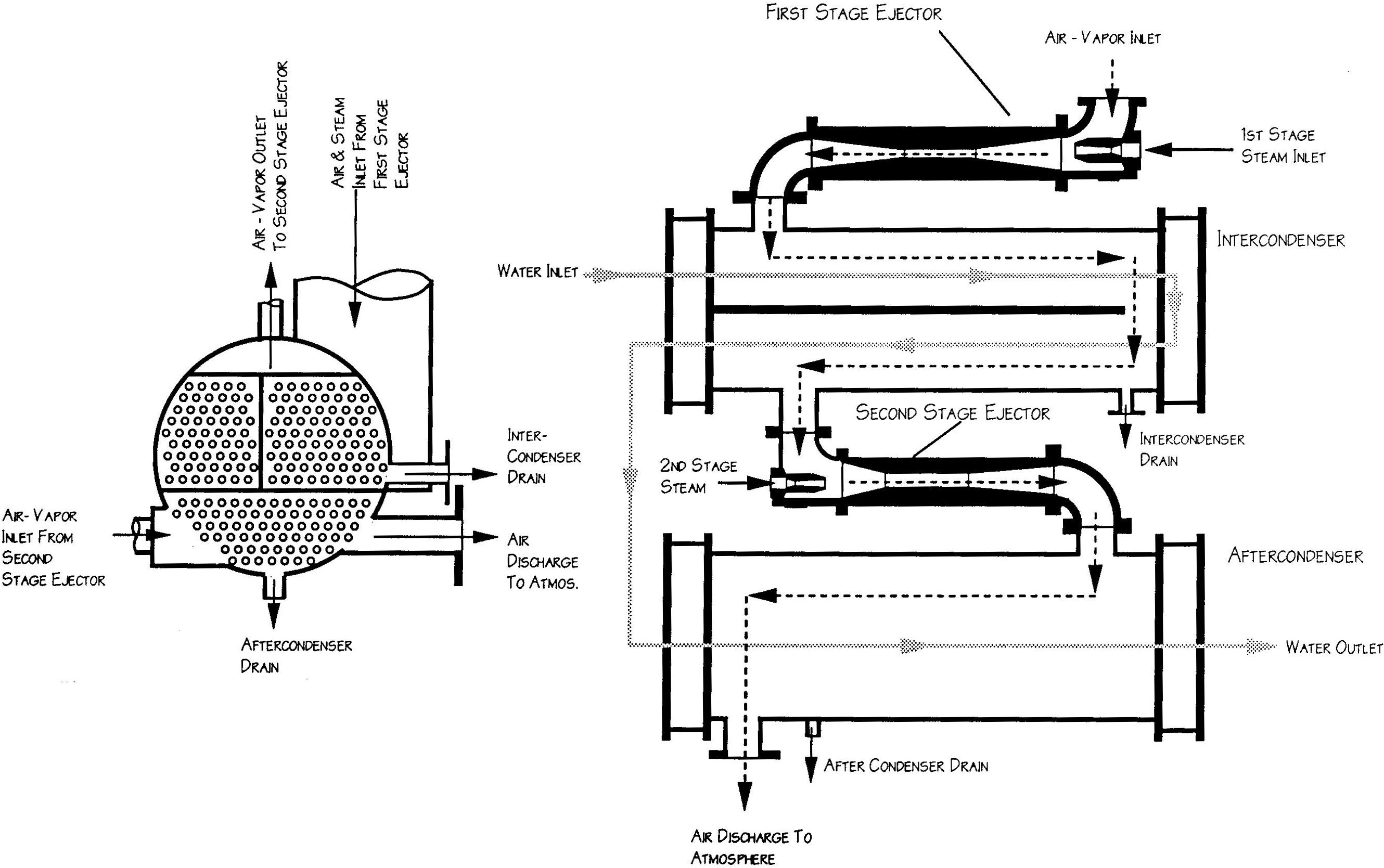
Two-stage Air Ejector
The combined first stage heater, gland exhaust condenser, and drain cooler is placed in the condensate system between the air ejector condensers and the D.C. Heater. Its function is to preheat the condensate and recover heat energy.
The feed heater section of the unit received its steam supply from the low pressure bleed line of the main propulsion unit. Drains from the heater section flow into the drain cooler section of the unit. This drain cooler section receives drains from the heater section of the combination unit and uses them to heat incoming condensate and then discharges them to the main condenser via a pilot controlled, air actuated drain regulator. If a malfunction occurs, the regulator may be secured and the flow regulated through a hand operated, close adjustment type valve in series with the regulator. The gland exhaust condenser section receives gland exhaust steam leakage from the main propulsion and generator turbine glands, D.C. heater vent, and any flash vapor from the drain collecting tank. Non-condensable gases and vapors are discharged to atmosphere by the gland exhaust fan.
Condensate first enters the drain cooler section where its temperature is increased by the heat remaining in the first stage heater condensate. Then it passes through the gland exhaust condenser section, where it picks up more heat while simultaneously condensing the steam which leaks from the H.P., L.P. and feed pump turbine glands. Finally, the condensate passes through the first stage heater section, where it is heated to approximately 180° by L.P. bleed steam.
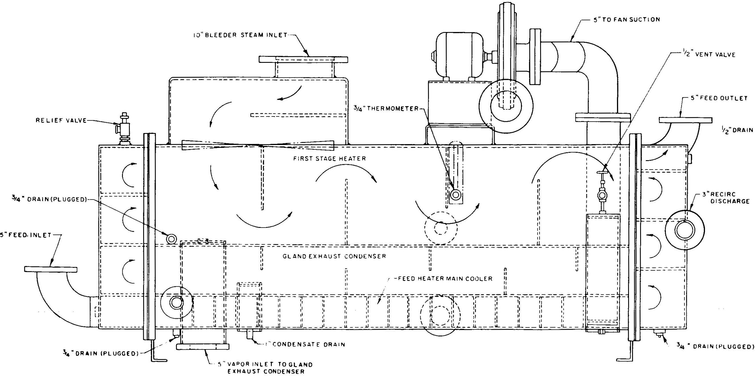
First Stage Heater, Gland Exhaust Condenser, and Drain Cooler
The second stage heater aboard the Patriot State is called the D.C. Heater for Direct Contact Heater, or the DFT for Deaerating Feed Heater. The second stage feed heater is of the direct contact, storage type.
The function of the D.C. Heater is threefold:
Condensate enters the second stage heater where it is broken up into a fine mist. Heating steam supplied from the auxiliary exhaust system flashes the mist to vapor and this causes entrained gasses to be liberated. The heated and deaerated water then drains to the reservoir of the tank and provides feed for the boilers. The liberated air and non-condensable gases are vented to the gland exhaust condenser.
High pressure steam drains from the whistle, contaminated evaporator tube nest, Butterworth heater, third and fourth stage feed heaters, and the external desuperheaters are returned to the D.C. Heater.
In the event of failure of the D.C. Heater it may be by-passed by directing condensate from the first stage heater to a reserve feed tank in the double bottom, and using the in-port feed pump to take suction from the same tank to feed the boiler.
The D.C heater is manufactured Worthington, and is of the vertical, steam jet type. Its storage capacity is 3000 gallons with a flow capacity from 120 to 370 lbs per hour while raising the temperature of the feed from 183 to 359° F. Its operating pressure is 20 psi. The D.C. heater is fitted with a relief valve set at 35 psig, a vacuum breaker, gauge glasses, remote reading liquid level indicator and vent.
The Nash Vacuum pump was installed in 1991, and is representative of equipment found on modern merchant ships. The purpose of the vacuum pump is to create and maintain the vacuum on the main condenser, and it can be used as a back-up and alternative to the main air ejectors.
The vacuum pump has two-stage rotor which is turned by an external motor. One portion of the rotor lies within a first-stage chamber that is formed by the casing, the other portion of the rotor lies within the second stage chamber. Both pump stages function identically. The operation of the vacuum pump is shown in the illustration. Pumping is made possible by the fact that the axis of the casing is offset from the axis of the rotor. The offset in the second stage is diametrically opposite the offset in the first stage.
Water is admitted to the first stage chamber through a passage in the cone, and acts as a seal liquid. Additional seal water is fed directly to the vacuum pump from the heat exchanger to seal clearances in the vacuum pump.
The Air/water vapor mixture from the condenser is drawn in through the air inlet. A spray nozzle in the cone forms the seal water into a spray pattern through which the air/water vapor mixture must pass. At the point, most of the water vapor condenses. Then, the pumped gasses and seal water are discharged through the first stage discharge passage to the second stage at increased pressure. Finally the air and seal water is ejected at atmospheric pressure through the air discharge to the separator.
In the separator, the seal water drops from the air stream to the bottom, and the air vents out the top. An automatic float switch and make-up solenoid valve, and an overflow loop maintain the proper level of seal water.
After it passes through the pump and separator, the seal water is circulated through a heat exchanger, and then back to the pump.

Vacuum Pump principle of operation

Nash Vacuum Pump
A Salinity indicating system is installed to detect the presence and source of salt in the feedwater system and thus guard against its discharge to the boiler. There is a salinity indicator panel mounted on the main operating platform near the main switchboard. This panel indicates the salinity readings measured by cells located at
The salinity indicating panel and its associated alarm light and horn give visible and audible warning when condensate salinity as measured by any cell exceeds 0.25 grains per gallon. When any alarm sounds, the cause should be ascertained and steps taken to correct the condition.
Direct comments to William Haynes whaynes@maritime.edu
Mon, Jul 1, 1996
TSPS Engineering Manual ©1995 Massachusetts Maritime Academy