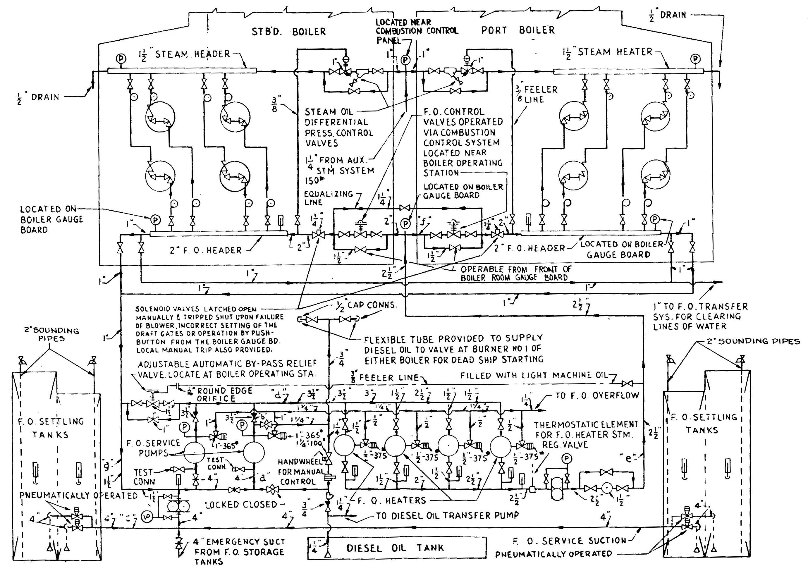
Fuel OIl Service System
Patriot State was the training ship of the Massachusetts Maritime Academy from 1986 to 1998.
The fuel oil service system is designed to deliver fuel oil to the boilers at temperatures and pressures suitable for satisfactory combustion. The system basically consists of settling tanks, suction and discharge strainers, pumps, heating coils, seven valves to properly meter fuel and other assorted hardware.
The four settling tanks are located in the after portion of the engine room. These tanks are filled and replenished via the fuel filling and transfer system. Each tank is provided with low and high suction valves, the latter of which can be pneumatically controlled from the bridge deck if necessary. Also, sounding tubes on each tank and remote level indicators are provided for oil level detection within each tank. Heating coils are located in each tank to heat the fuel oil to 110° F.
The two fuel oil service pumps are arranged to take suction from the low and high suction valves as well as an emergency suction from the transfer system which permits the pumps to take suction on any storage tank if necessary. Suction strainers between the tank and the pumps serve to strain foreign particles, which if allowed to pass, could clog the pumps or the burner nozzles. The accepted practice on this ship is to use the high suction on the settlers.
After passing through the pumps, the oil passes through any one or more of four fuel oil heaters each of which is capable of heating 4250 lbs/hr. of Bunker "C" oil from 100° F. to 230° F. when supplied with steam at 50 psig. Steam to the heaters is supplied from the 65 psig system. The heaters are fitted with thermostatically operated steam supply valves which receive an impulse from the fuel oil heater outlet thermostatic element in order to maintain a constant temperature at the burners. Relief valves are provided on each shell which are set at 375 psig to relieve fuel oil back to the settlers.
Fine mesh discharge strainers are located after the heaters in front of the starboard boiler to strain particles which might clog the burner tips. A fuel meter at the discharge side of the strainers measures the flow of oil to the burners. This meter may be isolated by means of a valved by-pass and gate valves on each side of the meter. This is normally used when recirculating the oil on start up.
Since it is not possible to control the capacity of the fuel oil service pumps, except by means of two speed motor drive, an automatic by-pass relief valve is provided to permit the unloading of excess oil at varying boiler loads and thus maintain a constant pressure in the line to the oil control valve. An actuating line for this regulator senses the pressure just prior to the combustion control valves. This valve is installed at the discharge of the fuel oil pumps, and automatically recirculates excess oil back to the suction of the pump.
Two fuel oil control valves are operated through impulses from the combustion control system and regulate the header oil pressure in relation to boiler load. Manual by-pass valves are provided in case the automatic valve malfunctions, and an equalizing line is provided to equalize the header pressure between the two boilers if the two valves happen to have different settings which otherwise might cause unequal steaming rates.
Solenoid trip valves, in the line between each fuel oil control valve and its burner header, are latched open manually and will automatically shut when:
In order to latch open the valve, the solenoid must first be energized. The solenoid con only be energized when its associated forced draft blower is in operation.
At the fuel oil header, oil is piped to individual burners. Piping is provided at the fuel oil header to recirculate oil to the suction side of the service pumps to allow heating fuel oil during start ups. Also, a diesel hose connection from the diesel tank can be piped through the fuel oil service system to one burner for cold-plant start ups since diesel fuel need not be preheated. Further, a piping arrangement is provided to send fuel oil back to the transfer system. Lastly, pressure within each fuel oil branch acts as the activator of the steam atomizing regulating valves to ensure proper atomizing steam pressure at each burner.
Two motor driven service pumps supply the fuel oil service system. These pumps are vertical, rotary, 2-speed units having a capacity of 20/40 gpm, at 350 psig discharge pressure. The pump discharges are fitted with relief valves set at 365 psig which relieve to the fuel oil settling tank. Speed selection for the pumps is controlled from the fireroom gage board.
There are two sets of duplex strainers in the fuel oil system. The strainers are of the basket type. The first duplex strainer set is found in the fuel oil line before the fuel oil pump. The second duplex strainer set is found in the fuel oil line after the fuel oil heaters. The first strainers have a larger (course) mesh and the second set has a more narrow (fine) mesh.
A differential pressure gauge which reads the pressure drop across the strainers indicates when a strainer requires cleaning. Cleaning a strainer involves first switching the flow over between strainers. This is accomplished by a plug valve. When flow has been assured, the initial strainer is opened, the basket cleaned, and reinstalled. Strainer switch over and cleaning is done when a pressure drop exists across that strainer of ten pounds.
Before starting up the fuel oil service system, the fuel oil settling tanks should be full and heated, if necessary, to the proper temperature for pumping. Suction valves on the two inboard or two outboard settlers should be opened. The by-pass valve around the fuel oil meter should be opened so that recirculated oil does not register on the meter. The service pump and fuel oil heaters should be lined up, but don't put steam on the heaters until after the pump has been started. After the forced draft fan has been started, the solenoid valve can be latched open. Open the recirculating valve slightly and start the pump. Oil is recirculated through the heaters until the proper temperature for atomization is reached. Care must be taken to avoid overheating the oil because this can cause vaporization of the fuel, leading to loss of suction at the fuel pump. This is particularly important when recirculating for the second boiler, because loss of fuel suction will affect the steaming boiler.
Fuel OIl Service System
Direct comments to William Haynes whaynes@maritime.edu
Mon, Jul 1, 1996
TSPS Engineering Manual ©1995 Massachusetts Maritime Academy