Evaporator Cycle: Units Number 1 and 2
Patriot State was the training ship of the Massachusetts Maritime Academy from 1986 to 1998.
There are four evaporators installed aboard the Patriot State to make fresh water from seawater for boiler feed and for drinking. Units one and two are the original units installed when the vessel was built. Unit three was installed in 1985 when the ship was converted to training ship use, and unit four was installed in 1993.
All four evaporators are flash-type evaporators. Flashing is vaporization (boiling) which occurs when the pressure of water is suddenly lowered below the saturation pressure corresponding to the temperature of the liquid. You can observe flashing whenever a hot steam drain valve is opened to the bilge.
In a flash type evaporator, heated salt water passes through an orifice into an area of lower pressure which is created by an air ejector or vacuum pump. A portion of the water flashes into steam, and the steam passes up to a vapor separator, where water droplets are removed, and then to a distilling condenser where the vapor is condensed. In a two-stage evaporator, water is drawn into the second stage by a lower pressure and the flashing/condensing procedure is repeated.
The condensed vapor is called distillate. It is cooled in a distillate cooler, and then pumped through a 3-way valve and, if its salinity is satisfactory, to the storage tanks.
Water that does not flash in each stage is called brine and is pumped overboard. Brine has a higher salt concentration than the original salt water.
The main advantage of flash evaporators over other types is that it operates at low temperature. The temperature does not go above 170° F. At low temperatures, scale formation is minimized, and this enables prolonged operation at maximum efficiency. Whatever scaling does occur, takes place on the inside of heat transfer tubes. It is mainly soft carbonate compounds which are easily removable.
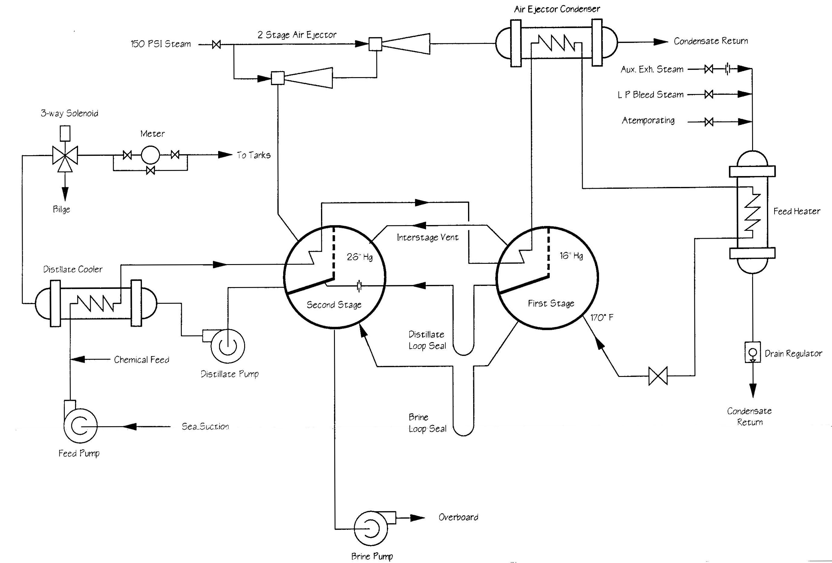
Evaporators one and two were constructed by Bethlehem Steel Company and are rated at 20,000 gallons per day. They are located on the operating level port side.
The heating steam used is either auxiliary exhaust, or steam bled from the low pressure turbine at 9.4" Hg Absolute and fed into the distiller salt water feed heater. Here the salt water is heated to 165° F. by adjusting the amount of steam admitted to the heater and the rate of flow of salt water through the heater. The steam has no direct contact with the water in the system. The condensate from the heater is drained by vacuum drag through a drain regulator to the auxiliary condensers, bilges or the ADT. The salt water is taken in at a sea chest, goes through the salt water circulating pump, through the distillate cooler, to the second stage condenser, to the first stage condenser, and then through the distiller air ejector condenser and then to the distiller salt water feed heater. By now the feed water is up to 170° It enters the first stage where some flashes and then condenses. The remaining feed water goes into the second stage. Again, some flashes and the rest goes overboard through the distiller brine overboard pump. The water which condensed in the two stages is now known as distillate. Distillate from the first stage passes through a loop seal into the second stage where the distillate pump takes a suction and pumps the distillate through the distillate cooler, three way solenoid valve, a water meter and then to the fresh water receive system.
Unit one has an air ejector built by C.H. Wheeler Co. of the single two stage noncondensing type. It must have a minimum of 130 psig steam to operate properly. The steam is condensed in the air ejector condenser and condensate drains to the bilge or it is vacuum dragged to the auxiliary condensers. Air and non-condensable gases are vented at the top of the condenser.
Unit two uses a vacuum pump in place of the removed air ejector and condenser. It also is equipped with a seal water cooler which uses the domestic glycol system for coolant.
The salinity indicating system was manufactured by McNab Inc., model M-ATC-S. Indicating cells are located in the following locations in each distilling plant.
Cell no.
	2  Air ejector or vacuum pump drains
	3  Salt water heater drain
	4  Distillate loop seal
	5  Distillate before cooler
	6  Final distillate
The distilling plant has two feed pumps.
Pump
     Manufacturer:   Ingersall Rand
     No. per ship:   2
     Type:           Horizontal, motor driven, single stage,centrifugal
     Capacity GPM:   300
     Total head ft.: 70
     RPM:            350
Motor
     Manufacturer:   General Electric Co.
     RPM             3600
     H.P.            7.5
     Phase           3
     Voltage         440
     Winding         squirrel cage
     Cycles          60
     Weight (lbs.):  290
These pumps take water from the sea chest through the four heat exchangers and into the salt water heater. From there, the water goes into the first stage.
There are two distilling plant distillate pumps:
Pump
     Manufacturer:   Warren Pumps, Inc.
     No. per ship:   2
     Type:           Horizontal, motor driven, single stage, centrifugal
     Capacity, gpm:  20
     Total head ft.: 100
     RPM:            3500
Motor
     Manufacturer:   General Electric Corporation
     RPM             3600
     H.P.            3
     Phase           3
     Voltage         440
     Winding         squirrel cage
     Cycles          60
These pumps take a suction from the second stage of the evaporator and pump the distilled water through a three way solenoid valve, a water meter, and to either the reserve feed tanks or the potable water tanks.
There are two distilling plant salt water overboard discharge pumps:
Pump
     Manufacturer:   Warren Pumps, Inc.
     No. per ship:   2
     Type:           Horizontal, motor driven, single stage centrifugal
     Capacity gpm:   285
     Total head ft.: 86
     RPM:            1750
Motor
     Manufacturer:   General Electric Corporation
     RPM             1800
     H.P.            15
     Phase           3
     Voltage         440
     Winding         squirrel cage
     Cycles          60
These pumps take a suction from the second stage of the evaporator and pump the brine, which did not flash and has a high concentration of salts, overboard.
Evaporator Cycle: Units Number 1 and 2
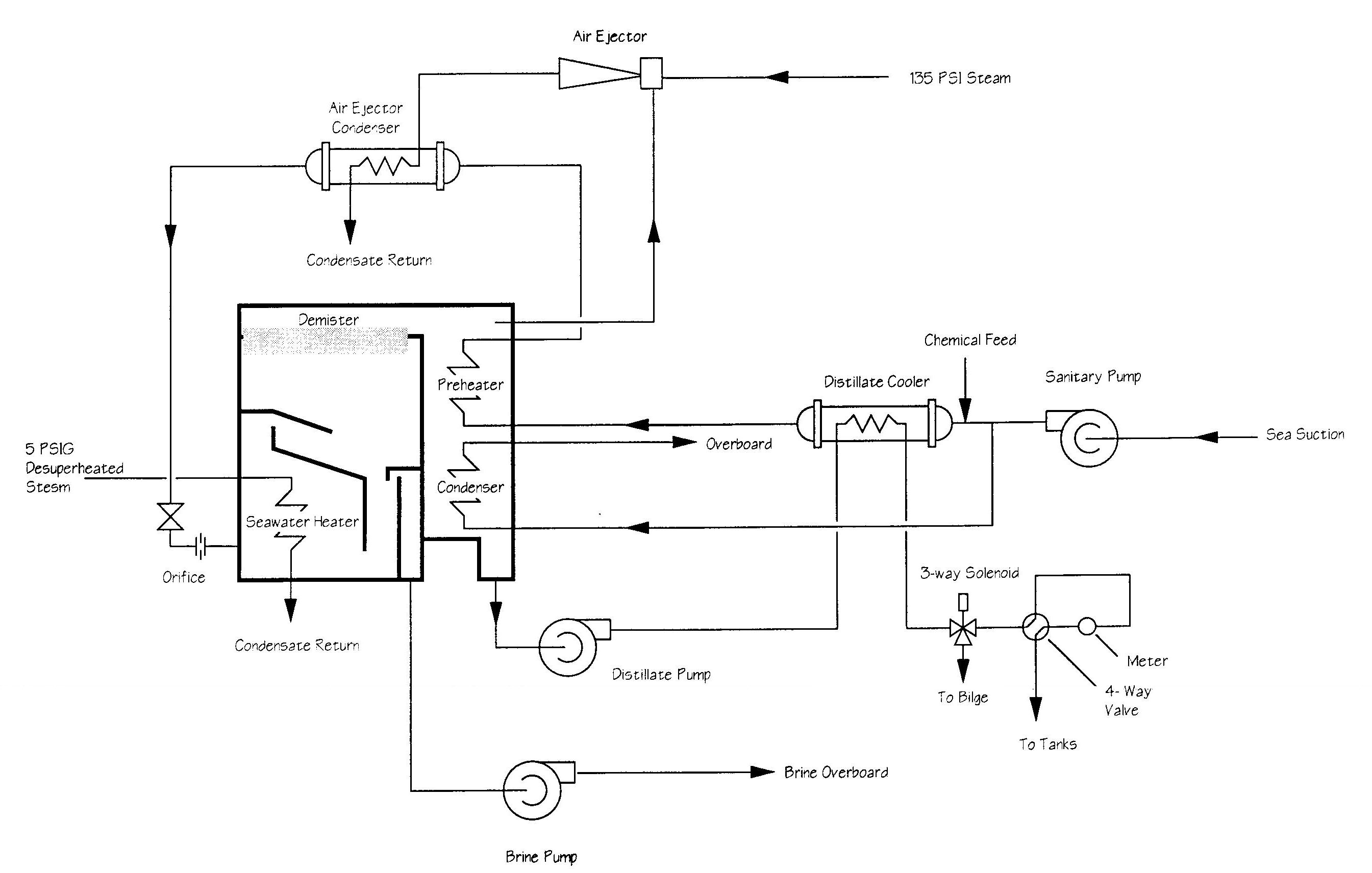
Distilling unit number three is located on the lower level port side aft. It was made by Riley-Beaird Inc., and is a single stage flash evaporator. Sea water for the unit is supplied from the sanitary system. Steam is supplied from a reducing station which supplies 135 psi steam for the air ejector and 5 psi steam for the sea water heater. Condensate is vacuum dragged to the auxiliary condenser.
Sea water from the sanitary system passes through a supply control valve, then a major portion of the water passes through the distillate condenser and then overboard. The remaining water is fed and passes through the distillate coolers, preheaters, air ejector condenser, then through a constant flow orifice which maintains a flow of 35 gallons per minute and into the sea water heater. It is pulled by the vacuum into the shell through a nozzle from the heater where it flashes; the vapor passes through mesh separators and is condensed by the preheater and condenser. The distillate is pumped through the distillate coolers and to the automatic solenoid valve. If the salinity is below .25 grains per gallon, the solenoid valve closes and the distillate passes through the meter and out to the tanks.
The salinity indicating system was manufactured by McNab Inc., model MDM-ATC-10-4D-DS. Indicating cells are located in the following locations:
cell number:
	1. Final distillate
	2. Distillate before coolers
	3. Air ejector condenser drains
	4. Heater condensate
The salinity indicating system is also equipped with a low sea water feed temperature alarm which automatically trips the solenoid valve to the bilge if the temperature of the feed water falls below 165° The alarm has a delay of 15 minutes after the temperature has been restored to 165° F. before the solenoid valve will reset.
Evaporator Cycle: Unit Number 3
Evaporator number four is a flash evaporator that uses plate-type heat exchangers instead of shell and tube heat exchangers found in the other units. This unit is manufactured by Alfa-Laval Company and Nirex heat exchangers. The unit is rated at 95 m3/day (approximately 25000 gallond/day ), and is located on the upper level, port side, in the space previously occupied by the number 2 air conditioning compressor.
The purpose of a plate-type heat exchanger is to transfer heat from one fluid to another. The heat passes very easily through the thin plates separating the two fluids.
The theory of operation is as follows: Heated salt water is introduced into the evaporator section of the evaporator through an orifice, and is distributed into every second channel (evaporation channels) of a plate-type heat exhchanger. Hot water, heated by steam from the 150 psi system, flows through the remaining channels, and transfers its heat to the sea-water.
When the feed water reaches its boiling point, which is lower than 212° F because of the vacuum in the shell, it undergoes a partial evaporation and the mixture of vapor and brine generated enters the separator, where the brine is separated from the vapor and extracted by the combined brine/air ejector. The demister removes any remaining water droplets from the vapor and feeds it into the condenser where it is cooled and returned to liquid form. It is then pumped through a three-way valve an on to the storage tanks.
The main advantage of this evaporator is that the temperatures are low since evaporation takes place in vacuum. This limits scale formation. Also, the plates are designed to create a very turbulent flow for the fluid motion - this inhibits heavy scale formation.
The main components of this unit are as follows :
Separator : In this section brine boils into vapor and it encloses the evaporator section, the condenser and the demister. It separates vapor from brine.
Evaporator section : It consists of a plate heat exchanger, where a package of plates are compressed together and the holes at the corners form continuos tunnels for the brine and hot water. Both the fluids are distributed into the narrow passages between the plates and they never come in direct contact with each other. The heat is transferred from the hot water to the brine which is colder.
Condenser : It is a similar plate type heat exchanger as described above for the evaporator section. As the vapors rise they are condensed by the sea water . In this process the sea water gets heated and after the flow has been established the sea water is fed into the evaporator.
Ejector pump : It supplies the condenser with sea water for cooling and brine/air ejector with jet water as well as feed water for evaporation. It is rated at 3440 RPM and 1.8 KW.
Freshwater pump : It extracts the produced freshwater from the condenser and transfers the water to the freshwater tanks. It is rated at 3525 RPM and 23 KW.
Combined brine/air ejector : The ejector extracts brine and air from the separator vessel. It discharges the excess sea water from the condenser and the separator shell overboard.
Salinometer : It continuously checks the salinity of the produced water which is 0.25 grains per gallon. It is located at the freshwater pump discharge. If the salinity of the water exceeds the above mentioned value it is automatically discharged to the bilge and a alarm is sounded on the control panel.

Evaporator Cycle: Unit No. 4 — Alpha-Nyrex
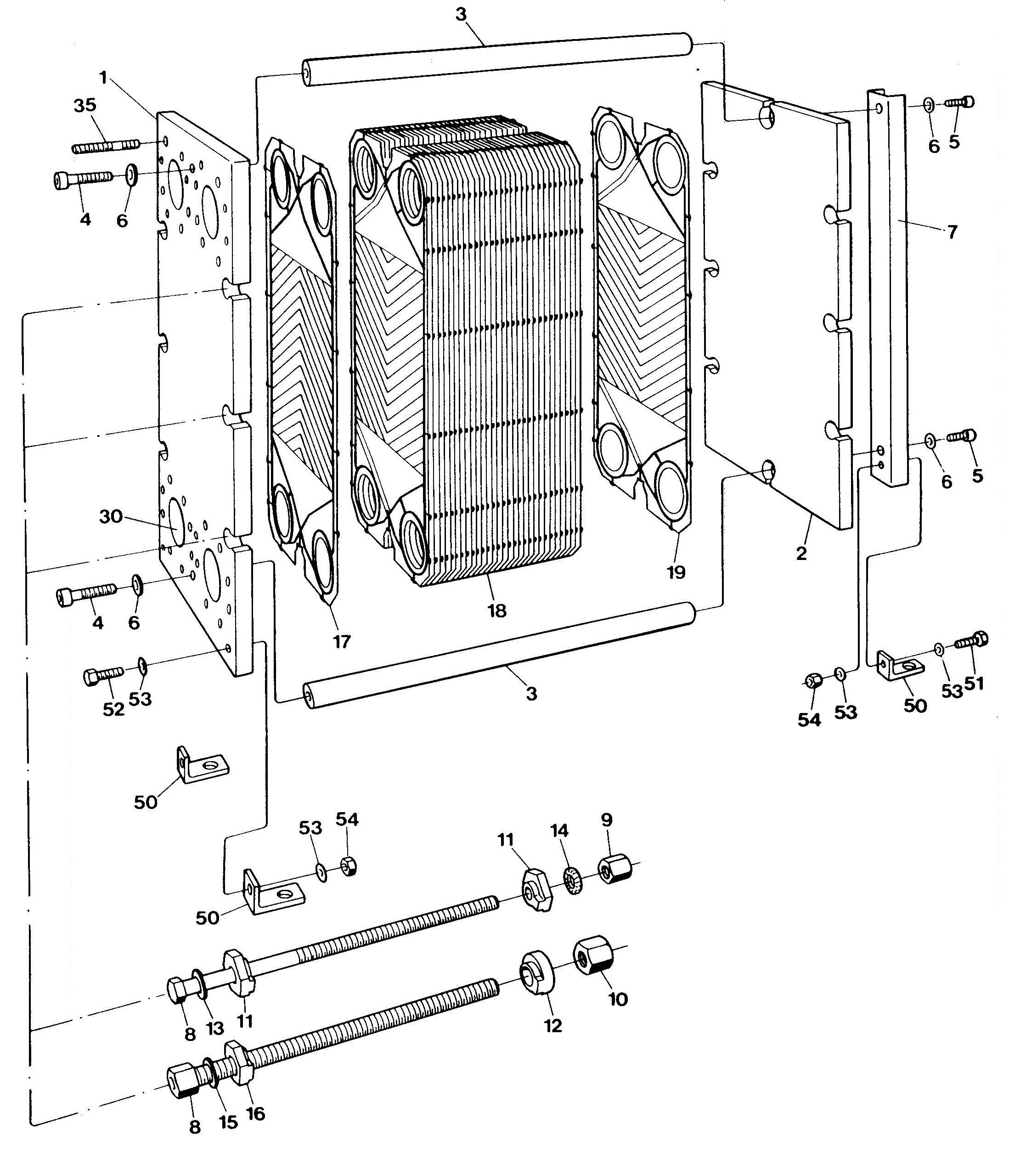
Plate Heat Exchanger
Direct comments to William Haynes whaynes@maritime.edu
Mon, Jul 1, 1996
TSPS Engineering Manual ©1995 Massachusetts Maritime Academy