Patriot State was the training ship of the Massachusetts Maritime Academy from 1986 to 1998.
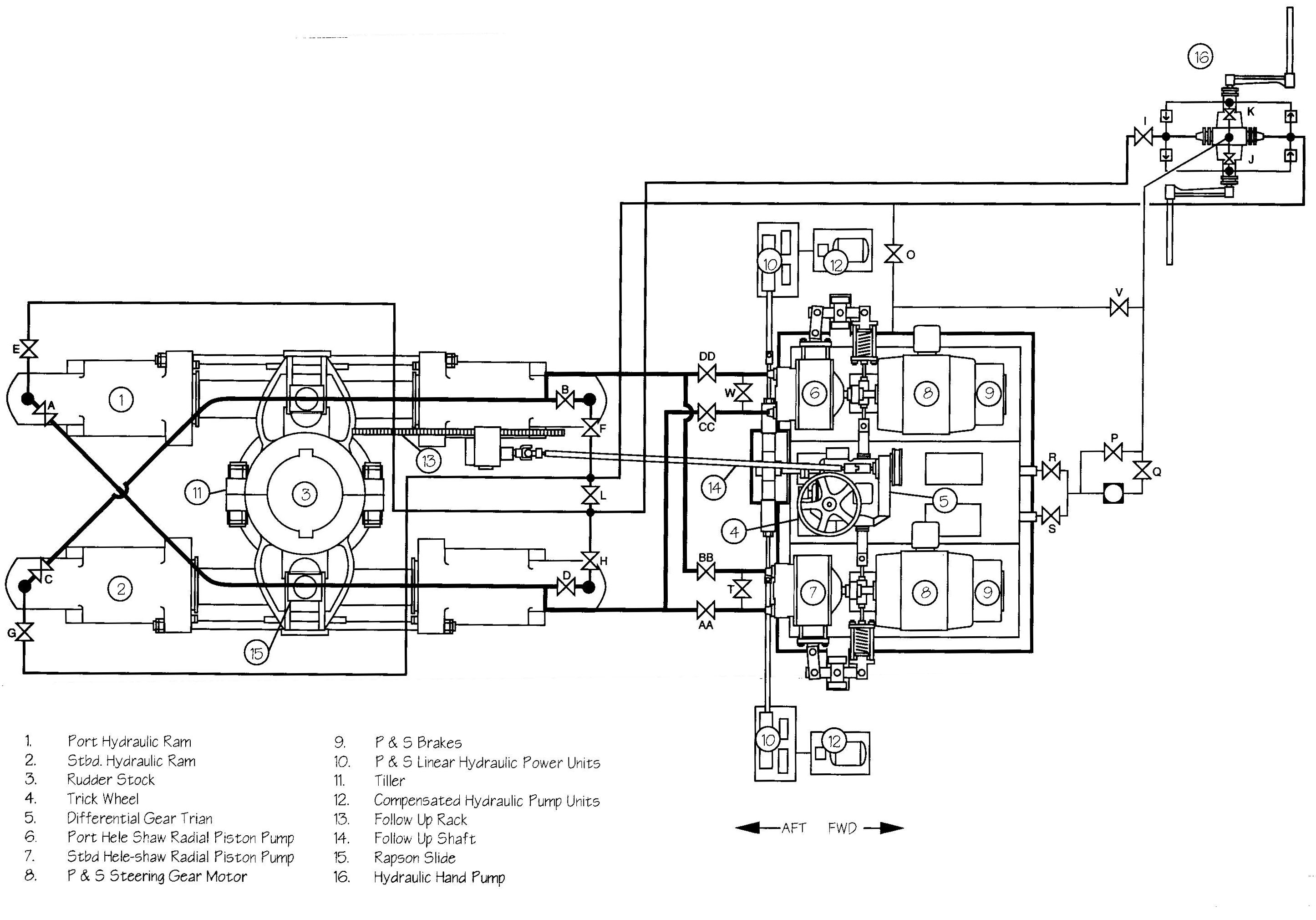
The ram assembly of the steering gear is connected to and moves the rudder stock in response to helm commands. It consists of two hydraulic rams and four cylinders and incorporates a full-storage-motion follow-up control system. There are two hydraulic power units, each consisting of a Hele Shaw variable stroke, radial piston pump, each capable of full ram movement by itself.
The rams are moved by the oil pressure built up in either pair of diagonally opposite cylinders. The oil from the other two cylinders, thus, flows t the suction side of the pump.
A tiller (item 11) is keyed to the top of the rudder stock and the force required to turn the rudder is transmitted through a Rapson slide mechanism (item 15 ) from the hydraulic rams.
The tie rods which connect the opposite cylinders also serve as guides for a sliding bracket attached to the rams, preventing that component from rotating. This bracket also provides mechanical limits to the ram travel at 36° of rudder angle. It contacts the copper facing on the stop collars and prevents further movement. If uncontrolled forces should cause further overtravel of the ram and complete disintegration of the copper, the steel stops will engage at 37° rudder angle.
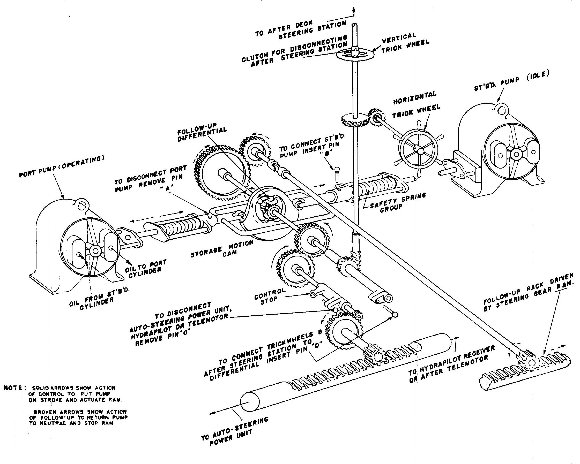
Whenever the bridge makes a change in helm command, the steering gear must immediately begin to move the rudder to the desired position. Ideally, the rudder should move quickly to the new position and then stop without overshooting. This control function is provided by the differential gear and follow-up mechanism. This mechanism measures the difference between the actual and desired positions of the rudder, known as the error, and to directs the radial piston pump to move the rams so as to reduce and then eliminate the error.
The differential gear train assembly consists of three bevel gears and a cam arrangement. One bevel gear is connected to the follow-up at the cam by shafting and universal joints. Another bevel gear is connected to the control system and trick wheel by a worm wheel and spur gear reduction unit. The third, or center bevel gear is mounted in a hardened cam. This cam is assembled and rotates between two adjustable hardened rollers mounted in a cradle, which is connected to the pump stroke control. The cam functions as a storage motion unit which permits the helmsman to operate the helm to a full rudder angle (35°) in either direction, at any input speed without damage to any control parts, or without any portion of the control getting out of synchronization.
The cam is designed with two short sloping sections of the periphery located diametrically opposite each and other and inclined in the same directions. These are used for placing the pump on working stroke. The high points of each incline are connected by a section of the periphery which is concentric with the center point of the cam and the low points of each incline are similarly connected. These concentric positions provide the storage motion for the control.
When the pump is in neutral position, the adjustable rollers in the cradle are located in the center of the inclined sections of the cam and any movement of the control will cause the cam to revolve. This motion of the cam causes the rollers in contact with the inclined surfaces to move toward and away from the center of the cam and this movement of the rollers is transferred directly to the pump stroke control. When the rollers have reached the high and low points of the cam, continued motion of the cam causes the rollers to pass along the concentric surfaces and no additional movement is transferred to the pump stroke. (The concentric portions of the cam provide for sufficient storage motion to permit revolving the steering or trick wheel within the limits of the stops on the control to produce 35° rudder angle of each side of midship position. They will also permit the steering and trick wheel to advance the control 70° ahead of the actual position of the rudder.
The follow-up mechanism consists of a follow-up rack (item 13) attached to the rams, and follow-up shaft (item 14) which transmits the ram position to the differential gear train. Any movement of the control from the linear hydraulic pump units or trick wheel places the Hele Shaw pump on working stroke and in turn moves the steering gear causing the follow-up rack to move and the follow-up shaft to rotate. When the steering wheel is brought to rest, the steering gear and follow-up gearing continue to operate until the floating ring of the Hele Shaw pump is brought to the neutral or no pumping position. After which the rudder is held at rest until another movement is required.
The follow-up mechanism prevents the over running of the rudder past the point selected by the helm.
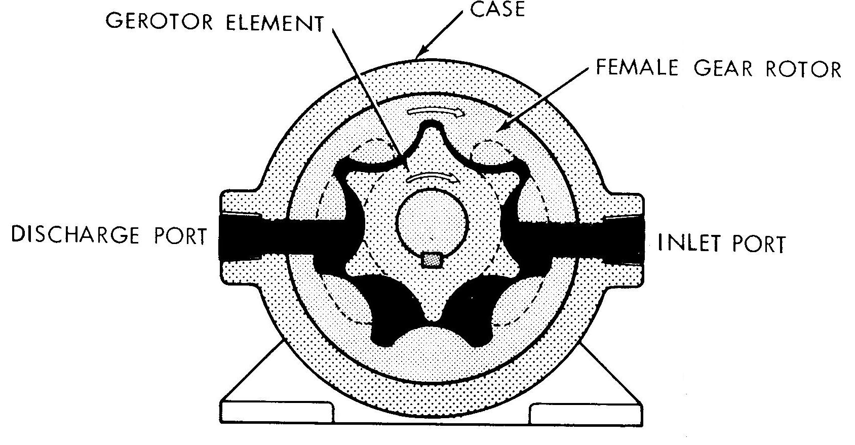
In event of failure of the variable stroke Hele Shaw pumps, the steering gear can be operated by use of the emergency hand operated O.H.M. Gerotor pump and the low pressure hydraulic piping.
The O.H.M. pump (Item 16, page 8-13) consists of two separate and independent Gerotor pumping units, each contained in separate chambered or pocket type head castings, which are fitted and bolted together to one central body, with integral pipe flanges. Each pump has its own drive shaft , anti-kickback assembly or brake, and hand crank.
The pump is fully reversible, the flow of oil changing by reversing the rotation of the crank. Each crank may be operated independently of the other.
The Gerotor pump is similar to an internal gear pump in that it contains 2 sets of rotating teeth, 1 set within the other. The inner Gerotor driven by the hand crank, has 1 less tooth than the outer Gerotor. As the 2 sets of teeth rotate together, (the outer Gerotor driven by the inner Gerotor) the teeth alternately engage and disengage. As the teeth disengage, the space between them increases in size, creating a partial vacuum into which the hydraulic liquid flows from the suction port. As rotation continues, the teeth begin to mesh together forcing the hydraulic liquid out the discharge port.
The hand pump has three main functions:
Refer to the steering gear manufacturer's chart located in the steering engine room for valve positioning and selection of rams to be used.
Each crank should be operated by two men and turned in the same direction of rotation. At 25 RPM, the pump will deliver approximately 2.5 GPM against a pressure of 450 psi. This high pressure is required only as the rudder approaches 15° or more. The cranks should be turned faster when rudder is nearer amidships in order to obtain maximum rudder movement in the shortest space of time.
The "anti-kickback" will prevent the rudder from "taking charge" so that the crank handles may be released at any rudder angle without danger of injury to the men that might otherwise be caused by reversing or overhauling rudder torque.
The hand pump can be used to fill and drain the system with hydraulic oil. Refer to steering gear manufacturer's chart located in the steering engine room for positioning of valves and direction of rotation of pump cranks for filling and draining the system.
The capacity of one pump (one crank) at 25 RPM is approximately 1.25 gpm at 450 psi. Should greater discharge be desired, the crank speed may be increased or the other pump may be operated. Since filling and draining pressures are relatively low, only one man is required for each crank for this service.
Both cranks must be turned in the same direction when both pumps are operated at the same time. It is not necessary that both cranks operate at the same speed.
By virtue of its anti-kickback or brake feature, the pump may be used for positioning and holding the rudder in place. During this service, a slight leakage of oil through the pump may be compensated for by an occasional turn of a crank. Any desired rudder position may be thus maintained.
Refer to the manufacturer's instruction chart for proper valving and for correct direction of rotation of pump cranks for desired rudder movement.
            Crank Speed   Pressure    Discharge   Viscosity of Oil
One Crank     25 rpm          450 psi        1.25 gpm      600 SSU at 100°F.
Both Cranks   25 rpm          450 psi        2.50 gpm      600 SSU at 100°F.
When the Hele Shaw pump is placed on stroke by moving the floating ring off the neutral position by either the linear hydraulic power unit or by the trick wheel, hydraulic fluid is pumped to the ram cylinders through the high pressure piping system (refer to the figure on page 8-13). The hydraulic piping between the pumps and cylinders is arranged so that either Hele Shaw pump can be used independently to supply the required power to operate the rudder, or so that both pumps can be used simultaneously for fast rudder speed. It is not necessary to adjust stop valves when changing from one Hele Shaw pump the other. As mentioned previously, to change from one pump to the other, you would depress the desired push button in the pilot house.
Stop valves are provided in the high pressure piping to be closed only for steadying the rudder in the event of an emergency or where repairing an idle pumps. The high pressure piping is equipped with relief valves to prevent damage to the steering mechanism due to excessive rudder shock which can occur when the vessel is in heavy weather or if some external object strikes the rudder. If the relief valves are lifted, the hydraulic oil is discharged back to the sump and the rams are allowed to move a slight amount. This movement is transmitted to the Hele Shaw pump by means of the follow-up gear and the pump is placed on stroke and returns the rudder to its original position.
Low pressure piping is provided for hand pump discharge pressure and to fill the system with the hydraulic oil. The piping to the cylinder connections is equipped with valves to isolate the low pressure piping when operating the Hele Shaw pumps.
Direct comments to William Haynes whaynes@maritime.edu
Mon, Jul 1, 1996
TSPS Engineering Manual ©1995 Massachusetts Maritime Academy