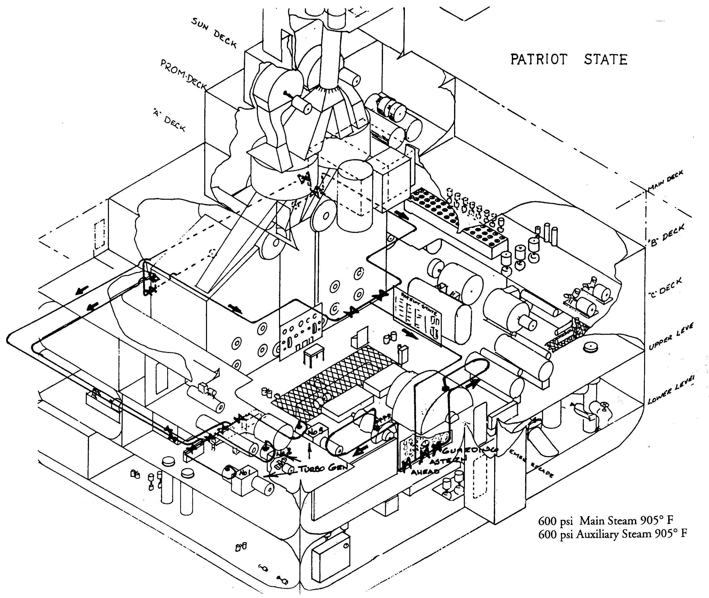
600 psi Main and Auxilary Steam (905 F)
Patriot State was the training ship of the Massachusetts Maritime Academy from 1986 to 1998.
The primary function of the main steam system is to furnish superheated steam to the main engine and turbo-generators. The system consists of two six-inch lines, one from each boiler, which lead into a single eight inch line. Connected into the lines at the boilers are two thermometers, one for local reading and one for distant reading on the boiler gauge board. The thermometer connected to the gauge board is also used to close a thermal switch activating an alarm when the temperature exceeds 915° F. To help in automatic control of the boiler there are pressure sensing lines going to the combustion control system and the feed pump governors. From the eight inch line the steam passes into a manifold containing a strainer, an ahead throttle, a governor valve and an astern throttle. On the inlet side of the manifold there are sensing elements for temperature and pressure gauges located on the main gauge board. A local thermometer is also provided. On each of the H.P. and L.P. turbines inlet lines there are sensing elements for the pressure gauges located on the main gauge board. A local reading thermometer is also provided here.
In the event of a casualty to the H.P. turbine, there is a portable 4" auxiliary steam line provided. This line may be connected to the L.P. turbine allowing the H.P. turbine to be blanked from the L.P. turbine. There is also a provision for by-passing the L.P. turbine should the need arise. This can be done by connecting the H.P. turbine exhaust into the exhaust casing of the L.P. turbine by using the 4" portable auxiliary line.
To prevent lines from bursting due to excessive pressure, relief valves are located on the main steam lines. The relief valve on this line is set to relieve at 645 psi. To insure no steam leaks to L.P. turbine, there is a guardian valve installed between the astern throttle and the L.P. turbine.
Drain lines are located on the main steam line to allow for draining condensate from the line to prevent water hammer when cutting in a system. Drain lines are also located on the superheater header, superheater temperature control lines and the superheated steam lines to the turbo-generator.
600 psi desuperheated steam is provided for the following purposes:
Main Feed Pump Steam Supply. The two main boiler pumps are supplied by a 2-1/2 inch branch line off the auxiliary steam main. This line is double valved. A strainer is installed at the inlet of the pump turbine governing system which is integral with the pump. The pump turbine governing system consists of a pneumatic differential pressure controller and a pneumatic-hydraulic speed governor. The hydraulic speed governor responds to an air pressure signal from the differential pressure controller and operated the turbine steam inlet valve so as to maintain a constant differential pressure across the feed water regulating valve as pump capacity varies from zero to rated flow. The differential is adjustable from 20 to 80 psi. In the event of air failure, the hydraulic speed governor will maintain constant turbine speed at the maximum setting of the governor. The governor permits manual adjustment of turbine speed while the unit is in operation.
Port Feed Pump Steam Supply. The port reciprocating feed pump is supplied by a 2 inch branch line off the main feed pump steam supply line. A stop valve is provided before and after and a by-pass valve around the constant pressure governor. A strainer is installed at the inlet of the governor.
The constant pressure governor throttles the steam supply to the port feed pump in response to variations in the pump discharge line.
Cargo and A.C. Turbo-Compressor Steam Supply. There is one operable turbine driven refrigeration compressor. It is supplied by a 3 inch branch line from the auxiliary main. (There were originally three turbine driven compressors. One was converted to electric drive and one was removed.)
The turbine speed is controlled by regulating the inlet steam by means of an air motor operated governor valve. The air motor used to control the governor valve is a control diaphragm device mounted on the steam inlet unit of the turbine so as to govern the speed control in response to diaphragm air loading. The air loading is from a pneumatic temperature controller having secondary refrigerant temperature as the controlling input. In the event the turbine speed reaches the setting of the speed limiting governor, the governor will override the control action of the air motor and limit the turbine speed to a set valve.
Soot Blower Steam Supply. The soot blowers for each boiler are supplied desuperheated steam at boiler pressure through a 2" branch line from the auxiliary steam main. Double valves prevent leakage of steam into soot blowers when not in use.
Reducing Stations. 600 psi desuperheated steam supplies 150, 135, and 125 psi reducing stations described below.
600 psi auxiliary desuperheated steam is supplied to a 4 inch auxiliary steam main, by either or both boilers from an external desuperheater in the main steam line. The external desuperheater is a 4 inch cartridge type unit and is furnished complete with automatic temperature control equipment and a bucket type steam trap. The automatic temperature control equipment consists of a 1 inch air operated diaphragm control valve and a temperature pilot complete with air pressure reducing valve, strainer, and air pressure gauges.
The desuperheated steam is maintained at 600° F. plus or minus 10° F. by a thermostatic regulator for the flow through the desuperheaters.
A stop valve before and after, and a by-pass valve around the diaphragm operated control valve are provided. A stop valve before and after, and a by-pass valve around the bucket trap is also provided. The high pressure traps drain to the D.C. heater. A local thermometer is provided on the desuperheater outlet steam line.
600 psi Main and Auxilary Steam (905 F)
Direct comments to William Haynes whaynes@maritime.edu
Mon, Jul 1, 1996
TSPS Engineering Manual ©1995 Massachusetts Maritime Academy