Feedwater System
Patriot State was the training ship of the Massachusetts Maritime Academy from 1986 to 1998.
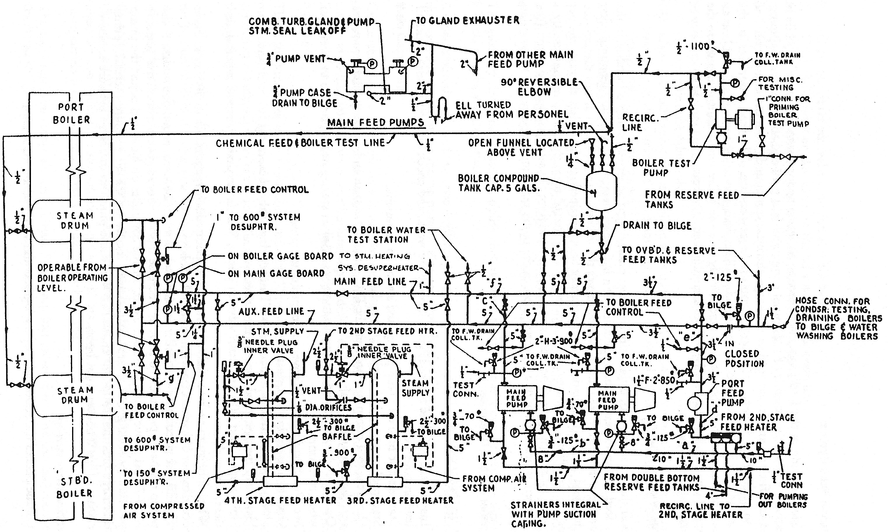
The purpose of the feedwater system is to preheated water at sufficient pressure to supply the boiler. The system consists of two turbine driven feed pumps, a reciprocating in-port feed pump, the third and fourth stage feed heaters, the main and auxiliary feed lines, the feedwater regulators, and the associated piping and valves.
Feedwater System
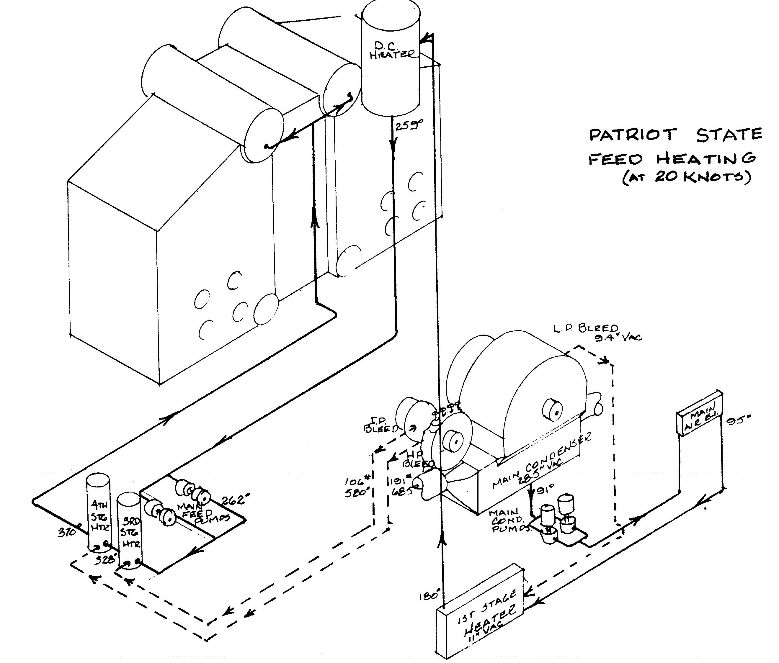
The third and fourth stage feed heaters are of the shell and u-tube type, having feed heating and drain cooling sections combined within a single shell. The third and fourth stage feed heaters receive steam from the intermediate and high pressure turbine bleeders, respectively. Drains from the fourth stage discharge to the third stage drain cooler section combine with the third stage drains and discharge to the second stage feed heater (described in the condensate section). Drains from both third and fourth stage feed heaters are controlled by pilot controlled regulating valves.
When the ship is operating at design power, the third stage heater raises the feed temperature from 262° to 328° F. while the fourth stage heater raises it from 328° to 370° F. At lower powers, the amount of feed heating is reduced due to the lower available steam temperature at the bleed points.
The process of using turbine bleed steam to heat feedwater is known as regenerative feed heating.
Feedwater Heating
There are two Pacific Marine Company horizontal, single stage centrifugal, turbine driven main feed pumps of 360 gpm capacity installed. Either pump has ample capacity to handle the maximum quantity of feed water needed under all conditions of operation. The feed pumps take suction from the second stage feed heater (D.C. heater) and discharge to the boilers through the main or auxiliary feed lines. The feed pumps supply feed to either the main or auxiliary feed lines, also they feed the external desuperheaters and the boiler compound tank. Boiler compound is injected into the system by the feed water pressure.
The two main feed pumps are supplied by a 2-1/2" branch line off the 600 psi desuperheated auxiliary steam main. This line is double valved and a strainer is installed at the inlet of the pump turbine governing system. This system is integral with the pump.
The pump turbine governing system consists of a pneumatic differential pressure controller and a pneumatic hydraulic speed governor. A differential governor is designed to maintain a constant difference in pressure between the feed pump discharge and the boiler drum.
The hydraulic speed governor responds to an air pressure signal set by the differential pressure controller, and it operates the turbine steam inlet valve so as to maintain a constant differential pressure across the feed water regulating valve as the valve opens and closes according to demand. The differential is adjustable from 20 to 80 psi. In the event of air failure, the hydraulic speed governor will revert to a constant speed governor, and hold the turbine speed at the maximum setting of the governor. The governor permits manual adjustment of turbine speed while the unit is in operation.
Rated Speeds for Speed Limiting Governor
Each main feed pump is equipped with a recirculating line which recirculates feedwater back to the D.C. heater. Recirculating is essential to prevent overheating of the pumps during low feed flow conditions such as low power and during start ups when the boiler feed regulators are closed. The recirculating line must be open at all times since pump balance is adversely affected if the line is closed.
Each main feed pump has two "Y" type strainers in the cooling water supply to the oil cooler. It is important that these strainers be cleaned regularly. Because of the small size of these strainers they can become clogged with a relatively small amount of material. While a clogged strainer is most likely to occur in port, or in shallow water, it can also happen at sea. So to prevent any problems and as a good preventative measure, the cooling water strainers on both the running and the idle feed pump shall be cleaned each watch.
To clean the strainer, first determine which strainer is on the line. This can be done by checking the inlet and outlet valves of each strainer to see which valves are open. Only one strainer should be on line at a time. Open the strainer cap of the secured strainer by unscrewing and remove the cap with the strainer screen attached. Clean all debris from the screen and then open the inlet valve to the strainer momentarily to flush out the strainer housing. Reinstall the strainer cap but do not tighten any more than is necessary to keep the cap from leaking. Open the inlet and outlet valves to that strainer and secure the inlet and outlet to the other strainer. Clean the other strainer in the same way and leave secured and ready for use.
These strainers should be cleaned a minimum of once each watch. However if the conditions warrant more frequent attention, they should be cleaned as often as necessary.
There is one vertical simplex, double acting, steam reciprocating in-port feed pump of 150 gpm capacity. This pump takes suction from either the second stage heater or the reserve feed tanks. The pump may discharge to the main or auxiliary feed lines, the reserve feed tanks, or the port or starboard filling stations on "B" deck. Additionally, there is a hose connection for condenser testing, boiler washing or draining the boiler to the bilge. The port feed pump, via a swing ell connection to the boiler blow piping, can pump down the boiler. The water wall tubes are drained through the headers to the bilge.
The port feed pump is supplied by a 2" branch steam line off the main feed pump steam supply. There is a by-pass valve around the constant pressure governor. A strainer is installed at the inlet end of the governor.
The constant pressure governor throttles the steam supply to the port feed pump in response to variations in the pump discharge pressure.
Provision is made in the feed piping for injecting boiler compound into either boiler while in operation. The system consists of a chemical compound feed tank and all the necessary piping, valves and fittings, and is arranged to discharge chemical compounds from the compound feed tank to each of the boilers, using feed pump discharge pressure. The feed water line to the compound tank is connected to the main and auxiliary feed lines so feed water is available at all times. The chemical compounds discharge directly into the boiler steam drums via a tee to the respective stop check and stop valves of the desired boiler. The compound tank has a capacity of approximately five gallons.
A motor driven, horizontal, duplex single acting, plunger type boiler test pump is installed in the boiler feed system to permit the application of a hydrostatic test to the boilers. The pump takes suction from the reserve feed tanks and discharges the feedwater to the steam drums through the chemical feed line. Hydrostatic test pressure may be maintained on the boilers through the use of this pump. Piping downstream of this pump is protected from the excessive pressure by a relief valve set at 1100 psig. The feed pump suction main from the second stage feed heater (the D.C. heater) is provided with a 1" connection to the boiler test pump suction line for priming the pump.
Direct comments to William Haynes whaynes@maritime.edu
Mon, Jul 1, 1996
TSPS Engineering Manual ©1995 Massachusetts Maritime Academy